- Tel:+8616638907067
- Email:[email protected]
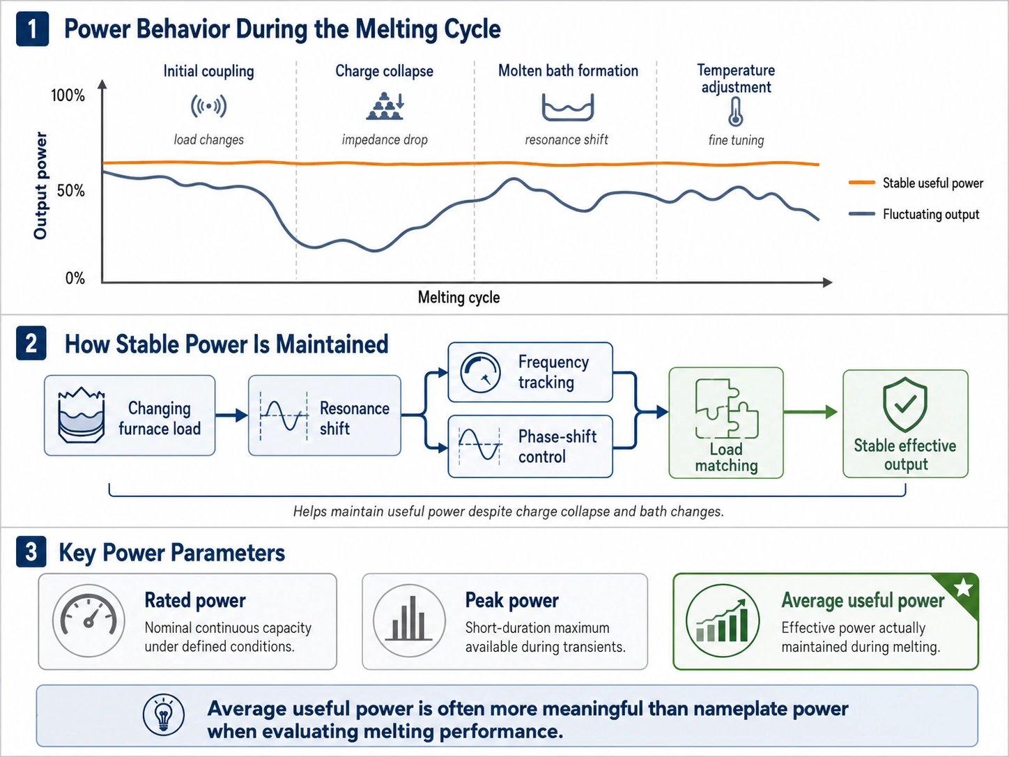
A constant power output induction furnace is valuable because the electrical load does not remain unchanged throughout a heat. Cold scrap, charge collapse, molten-bath formation, refractory condition, and temperature adjustment all change how effectively the furnace coil transfers energy to the metal. The rated kilowatts on a power-supply nameplate therefore do not tell the whole excerpt …
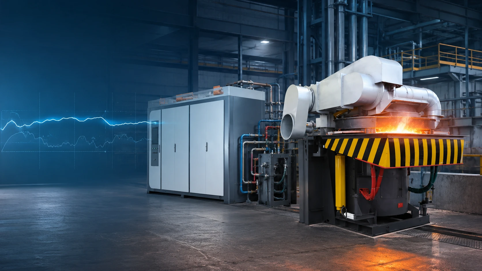
A constant power output induction furnace is valuable because the electrical load does not remain unchanged throughout a heat. Cold scrap, charge collapse, molten-bath formation, refractory condition, and temperature adjustment all change how effectively the furnace coil transfers energy to the metal.
The rated kilowatts on a power-supply nameplate therefore do not tell the whole production story. Buyers also need to know how much useful power the system can maintain as the load changes. More stable delivery can make melting time more predictable and reduce periods of low power, but it does not automatically guarantee lower electricity consumption per ton. The result still depends on furnace matching, charge preparation, operating practice, cooling, transformer capacity, and production delays.
An induction furnace is a dynamic electrical load. The power supply, capacitor bank, induction coil, refractory lining, and metal charge operate as one system. When the physical condition of the charge changes, the electrical characteristics seen by the power supply also change.
At the start of a cold heat, loose scrap may have poor or uneven electromagnetic coupling with the coil. Charge shape, piece size, packing density, oxidation, and the position of the scrap inside the crucible can all affect how energy enters the metal.
As the lower material heats and melts, unsupported pieces above it may suddenly collapse. Operators may then add more charge. Each of these events changes the effective resistance and inductance of the load. Voltage, current, operating frequency, and delivered power may move away from their earlier values.
A power supply that cannot respond effectively may experience a noticeable reduction in output during part of this process. Although its rated capacity has not changed, its average useful power over the heat may be lower than expected. Buyers comparing equipment should therefore ask how the system behaves during initial coupling and charge collapse—not only what power appears on the nameplate.
The furnace lining separates the molten metal from the induction coil, but its condition also affects electromagnetic coupling. Lining thickness changes over its service life, while temperature, sintering condition, cracks, repairs, and localized wear can alter the operating environment.
The metal bath also changes continuously. Its depth, temperature, electrical properties, and movement influence the load presented to the resonant circuit. A newly charged furnace, a partially molten furnace, and a full molten bath are not electrically identical conditions.
This is one reason a power setting that worked during one part of the heat may not deliver the same result later. Lining changes can also create safety and maintenance risks, so operators should never treat power fluctuation as a control problem alone. Abnormal power behavior may justify checking the charge, lining, coil, capacitor system, cooling, and electrical feedback signals.
In a series-resonant induction system, the induction coil and compensation capacitors form the principal resonant load. The system transfers power most effectively when the power supply operates within its designed matching and control range.
Because the charge and furnace conditions change, the resonant operating point can also shift. The control system must recognize these changes and adjust its output. Frequency tracking helps maintain the intended relationship between inverter frequency and the resonant load, while phase-shift regulation can control how much power the inverter delivers.
This does not mean the control system can overcome every physical limitation. A poorly sized transformer, an unsuitable coil, insufficient cooling, an incorrect capacitor configuration, or severely mismatched charge material can still restrict output. Buyers should confirm that the proposed control method is matched to the complete furnace system.
For a broader review of topology, frequency, transformer capacity, and site utilities, see the induction furnace power-supply selection guide.
Power figures should be separated before comparing furnaces or power-supply quotations.
| Power metric | What it describes | Why the buyer needs it |
|---|---|---|
| Rated power | The designed continuous or specified output under defined conditions | Identifies the nominal capacity of the power supply |
| Peak power | A short-duration maximum or instantaneous demand | Helps evaluate the transformer, switchgear, protection, and grid connection |
| Average useful power | The effective power maintained during a defined melting stage or complete heat | Helps evaluate melting time and production performance |
A 3,000 kW nameplate does not prove that 3,000 kW reaches the load throughout every minute of the melting cycle. The system may operate below that level during initial coupling, charge collapse, manual delays, temperature adjustment, or holding.
Average useful power is therefore highly relevant to production planning. It should be calculated over a clearly defined period, such as the powered melting interval or the complete furnace cycle. If one supplier excludes holding and stoppages while another includes them, the two figures are not directly comparable.
A useful operating curve should show power against time and identify major process events:
cold-furnace startup;
initial coupling with the charge;
charge additions and collapse;
molten-bath formation;
slag removal and temperature adjustment;
holding before tapping.
The curve should ideally be accompanied by voltage, current, and frequency data. Production records should identify the metal, batch weight, tapping temperature, lining condition, and significant operator delays.
A smooth curve is not automatically evidence of efficient melting. The important question is whether the system maintains appropriate useful power without exceeding coil, inverter, transformer, cooling, or process limits. A buyer should also check whether a graph is a measured customer result, an internal factory test, a simulation, or merely an illustrative curve.
For projects being sized by furnace capacity and hourly production, the IGBT power-supply sizing checklist provides the next level of selection detail.
Stable output matters because melting departments depend on timing. A furnace that regularly takes longer than planned can delay temperature adjustment, tapping, inoculation, pouring, and downstream molding operations.
When the power supply responds effectively to changing load conditions, it can reduce periods in which available equipment capacity is underused. This can make cold-start time and subsequent heat cycles more consistent.
The practical value is often production predictability rather than a universal percentage increase in output. Stable power cannot eliminate the time required for charging, slag removal, sampling, temperature correction, tapping, or relining. It also cannot correct bottlenecks in cranes, charging equipment, ladles, molding lines, or cooling systems.
Buyers should consequently compare complete heat records rather than an isolated maximum-power value. Useful indicators include:
powered melting time;
average power during melting;
total cycle time;
heats or tons per shift;
holding duration;
unplanned trips and restarts.
Energy consumption per ton can be represented in a simplified form:
kWh per ton = $\frac{\text{measured electrical energy within the selected boundary}}{\text{qualified molten metal produced}}$
More stable power may shorten the powered melting period or reduce low-output operation. However, kWh per ton is also affected by charge condition, tapping temperature, holding time, furnace lining, coil condition, cooling losses, production interruptions, and auxiliary consumption.
A furnace can maintain stable power and still record poor unit energy performance if molten metal waits for the pouring line or is overheated. Conversely, a lower-powered system may achieve acceptable kWh per ton but fail to meet the required hourly output.
Power factor must also be treated separately. It affects how electrical capacity is used, but a high power factor alone does not prove low energy consumption. Buyers should define the meter location and decide whether pumps, cooling towers, hydraulics, dust extraction, and holding loads are included. The induction furnace kWh-per-ton guide explains these measurement boundaries in more detail.
Constant-power capability should not be treated as the answer to every productivity problem. Its benefit may be limited when the main constraint is:
insufficient transformer or incoming-grid capacity;
an undersized or poorly matched furnace coil;
inadequate cooling-water flow or temperature;
slow or unsafe charging;
extended slagging, sampling, or temperature adjustment;
long holding periods caused by downstream production;
a worn lining or unresolved equipment fault.
In these cases, changing the control strategy alone may not improve plant output. The project should first identify where time and energy are being lost.
The phrase “constant power” may describe different control methods and operating ranges. A quotation should state what variable is controlled, how the system responds to load changes, and which limits cause power reduction.
Constant-current control limits or maintains current, which may be important for protecting power devices and the induction coil. Constant-voltage control regulates voltage within the system’s design limits. Constant-power control adjusts output so that power remains near a target when voltage, current, and load conditions change.
These modes are not necessarily mutually exclusive. An industrial power supply may change control or protection states according to startup, normal melting, abnormal load, or equipment limits. Buyers should ask for the control hierarchy instead of accepting a single marketing label.
An IGBT is an actively switched semiconductor device, but IGBT components alone do not produce constant power. The complete system requires a matched rectifier and DC link, inverter topology, capacitor-coil resonant circuit, voltage and current feedback, frequency tracking, gate-driver coordination, protection, and cooling.
SHENNAI technical documentation describes a capacitor-coil series-resonant architecture using phase-shift and phase-locked regulation. In buyer-friendly terms, the control system monitors the changing electrical load, follows the intended resonant operating region, and adjusts inverter output to support more stable power delivery.
The same documentation describes independently controlled power modules with separate drive boards and fast protection for short-circuit or abnormal-discharge events. These features are intended to reduce the risk that a localized device fault spreads into broader module damage. They do not eliminate every possible failure, and the available isolation or reduced-power operating mode depends on the selected configuration.
For buyers evaluating replacement or expansion options, the SCR vs IGBT power-control comparison explains why semiconductor type, circuit topology, protection, and maintenance scope must be reviewed together.
A meaningful constant-power assessment requires production and electrical information. The RFQ should include:
metal or alloy;
usable furnace capacity per heat;
target tons per hour and heats per shift;
cold-start and hot-furnace melting times;
tapping temperature and expected holding time;
number of furnace bodies and operating method;
existing power-supply type and rated power;
incoming voltage and utility frequency;
transformer rating and present loading;
coil and capacitor information for a retrofit;
cooling-water temperature, pressure, flow, and quality;
current kWh per ton, with its measurement boundary;
site altitude, ambient temperature, dust, and installation constraints.
The supplier should return more than a rated-kilowatt figure. Request a proposed control description, typical power curve, operating-frequency range, protection logic, cooling requirements, transformer assumptions, and a list of conditions behind any efficiency or production estimate.
If a supplier presents an energy-saving percentage, ask what system was used as the reference and whether the comparison used the same metal, batch weight, tapping temperature, lining condition, meter boundary, and production schedule.
SHENNAI’s full-bridge IGBT system is most relevant where a foundry values controlled output during changing furnace loads, predictable production, modular fault handling, and integration between the power supply and furnace body.
Its technical value comes from the combined series-resonant circuit, phase-based power regulation, feedback, independent drive modules, protection, and system matching. Final selection must still consider metal type, furnace capacity, hourly output, transformer, coil, cooling, and operating method.
The full-bridge IGBT melting furnace page provides the appropriate product path. In heavy-duty applications, the power supply may also be matched with a steel shell induction furnace, but the furnace body and power cabinet must be engineered as one system rather than selected independently.
Constant power matters during induction melting because the furnace load changes throughout every heat. Rated power shows nominal equipment capacity; it does not show how much useful power is maintained during charge collapse, bath formation, temperature adjustment, and holding.
Buyers should evaluate operating curves, average useful power, complete heat time, kWh-per-ton boundaries, protection logic, and system matching. Constant-power control can support more predictable melting, but energy and production results must be verified under defined operating conditions.
For a preliminary assessment, submit the metal, furnace capacity, target hourly output, existing power supply, transformer rating, cooling conditions, and available operating records when requesting a full-bridge IGBT power-supply quotation.
It may reduce low-output operation or shorten the powered melting interval, but it does not independently determine kWh per ton. Charge condition, tapping temperature, holding, furnace lining, cooling losses, operator delays, and the measurement boundary must also be considered.
They serve different purposes. Constant-power control targets stable energy delivery, while current control may protect power devices and the coil. A practical system may use several control and limiting modes at different stages. Buyers should review the complete control hierarchy.
No. Full-bridge topology and IGBT switching can support flexible regulation, but results depend on the resonant circuit, feedback, control software, module configuration, coil matching, transformer, cooling, and permitted voltage and current limits.
Provide the metal, batch capacity, required tons per hour, melting and holding cycle, input voltage, transformer rating, number of furnaces, existing equipment, cooling-water conditions, and available power or energy records.
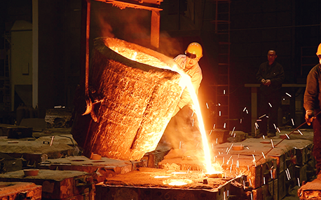
In the forging workshop, industrial furnaces smelt metals, including cupola, induction furnace, resistance furnace, electric arc furnace, vacuum furnace, open hearth furnace, crucible furnace, etc; There are sand mold drying furnace for baking sand mold, ferroalloy drying furnace and casting annealing furnace, etc; In the forging workshop, there are various heating furnaces for heating ingots or billets before forging and heat treatment furnaces for relieving stress after forging;
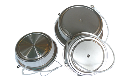
The most effective way for the failure of the medium frequency furnace is to use the low current experiment to judge whether it is the fault of the rectifier circuit or the fault of the inverter part. In the low current experiment, when the DC voltage is less than 513v, it indicates that there is a phase loss fault in the DC rectifier part. Check the specific thyristor fault, and the pulse breaking method should be used to judge whether it is the thyristor fault or there is no trigger pulse.
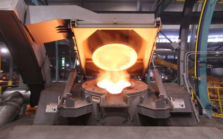
The most effective method for the failure of the intermediate frequency furnace is to use a small current experiment to judge whether the rectifier circuit is faulty or part of the inverter fault. When the DC current is less than 513 volts

Please send us your request and we will reply to you within 24 hours.
We will get in touch with you as soon as possible
