- Tel:+8616638907067
- Email:[email protected]
Choosing an induction furnace power supply requires more than comparing rated kilowatts or deciding whether SCR or IGBT sounds more advanced. The correct system must match the metal, furnace capacity, hourly production target, melting cycle, incoming grid, transformer, cooling conditions, maintenance resources, and future expansion plan. An IGBT system may offer greater control flexibility and excerpt …

Choosing an induction furnace power supply requires more than comparing rated kilowatts or deciding whether SCR or IGBT sounds more advanced. The correct system must match the metal, furnace capacity, hourly production target, melting cycle, incoming grid, transformer, cooling conditions, maintenance resources, and future expansion plan.
An IGBT system may offer greater control flexibility and modular protection in suitable applications. An SCR system may remain practical where high-power operation, established maintenance experience, or lower initial investment takes priority. The right choice is the system that delivers the required production output reliably under the actual operating conditions.
An induction melting system normally follows this energy path:
Three-phase AC input → rectifier → DC link → inverter → resonant circuit → induction coil → metal charge
The rectifier converts incoming alternating current into direct current. The inverter then converts that DC power into controlled medium-frequency current. The resonant circuit and induction coil create the alternating magnetic field that induces current and heat inside the metal.
The furnace body holds the refractory lining and molten metal, but the power supply controls frequency, output power, load matching, and electrical protection. For this reason, two furnaces with the same nominal capacity may have very different melting performance when their power supplies, transformers, coils, or cooling systems are configured differently.
A medium frequency power supply should therefore be evaluated as part of a complete melting system—not as an isolated electrical cabinet.
Both SCR and IGBT technologies are used in industrial induction equipment. The meaningful question is not which semiconductor is newer, but which complete power-conversion system fits the project.
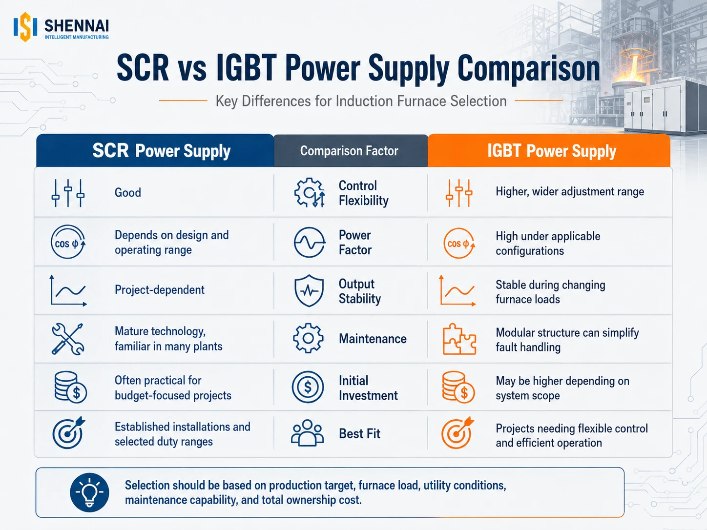
An SCR, or thyristor-based, power supply may remain a reasonable choice when the plant already has technicians, spare parts, and maintenance procedures for that technology. It may also suit projects where the selected power range, operating pattern, and investment priorities favor a mature thyristor configuration.
Before choosing SCR, buyers should confirm:
SCR should not automatically be treated as obsolete. Its suitability depends on the rectifier and inverter design, project scale, operating duty, and total ownership cost.
IGBT systems use high-speed semiconductor switching and can provide flexible output regulation. They are often considered when a foundry needs a wide adjustable power range, stable output during changing furnace conditions, higher input-side power factor, precise control, or modular fault handling.
However, the presence of IGBT devices alone does not guarantee lower energy consumption. Performance also depends on the resonant circuit, control strategy, component layout, cooling design, coil matching, and protection system.
| Comparison Factor | SCR System | IGBT System | What the Buyer Should Confirm |
| Initial investment | Project-dependent | Project-dependent | Complete supply scope |
| Power regulation | Depends on topology | Often more flexible | Output across the full load range |
| Power factor | Depends on design and load | Frequently a key design advantage | Guaranteed operating conditions |
| Maintenance | May suit established local skills | May support modular replacement | Spare parts and diagnostic method |
| Fault behavior | Depends on circuit protection | Depends on module independence | Extent of possible secondary damage |
| Operating cost | Depends on actual process data | Depends on actual process data | kWh per ton and melting cycle |
The comparison should always be based on tested system performance rather than technology labels.
“High efficiency” can describe several different measurements. Buyers should keep them separate.
Power factor is the ratio of real power used to perform work to the apparent power supplied by the electrical system. A power factor closer to 1 can reduce unnecessary current and relieve pressure on cables, switchgear, and transformers. It does not, by itself, prove that a furnace will achieve the lowest electricity consumption per ton.
Four indicators should be evaluated independently:
Actual kWh per ton is also affected by charge density, contamination, cold starts, tapping temperature, holding time, refractory condition, furnace delays, and operating practice. A supplier should therefore state the test conditions behind any claimed saving percentage.
The electrical load changes as cold material heats, the charge collapses, the molten bath forms, and the refractory lining condition changes. A nameplate rating only shows the maximum rated output. Production performance depends more on how much useful power the system maintains throughout the heat.
According to SHENNAI technical data, its IGBT power supply uses a capacitor-coil series-resonant circuit with phase-shifted, phase-locked power regulation. The stated objective is to maintain more stable output as charge and lining conditions change. For applicable configurations, the data lists a power factor of at least 0.97 and an energy-consumption improvement of approximately 3%–5% compared with a conventional thyristor reference system. These figures must be evaluated under the relevant furnace loading, metal, lining, production cycle, and system configuration.
A one-ton furnace does not have one universal power requirement. The necessary rating changes according to the metal, target tapping temperature, number of heats per shift, cold-start frequency, holding requirements, and desired hourly output.
A practical selection sequence is:
A lower-power furnace may meet the batch-capacity requirement but fail to meet the production target. Conversely, installing more rated power than the grid, coil, or cooling system can support does not create useful production.
Frequency influences electromagnetic penetration, current distribution, heating behavior, and bath movement. Higher frequency is not automatically better.
The appropriate frequency depends on factors such as:
The supplier should calculate frequency together with coil geometry, capacitor configuration, and furnace load. It should not be selected from furnace tonnage alone.
Before requesting a quotation, collect:
The choice between a steel shell induction furnace and an aluminum shell induction furnace should also be considered together with operating intensity, capacity, tilting requirements, workshop layout, and budget—not independently from the power system. SHENNAI currently positions steel shell furnaces for heavier-duty industrial operation, while aluminum shell configurations can suit more compact or cost-sensitive applications.
The production rhythm determines whether a project should use one power supply per furnace, one supply serving two furnaces, or a multi-output power-sharing system.
A dual-furnace arrangement may allow one furnace to melt while another holds molten metal. Industrial furnace suppliers use this approach to improve utilization of installed electrical capacity and coordinate melting and holding operations.
The buyer must clarify what “one power supply for two furnaces” means:
These are different control requirements. SHENNAI documentation describes one-to-two and multi-furnace arrangements with independent power regulation for specified systems, but the available operating modes and total output must be confirmed for the selected configuration.
A power-supply quotation should explain how the system responds to overcurrent, overvoltage, overheating, furnace short circuits, arcing, abnormal discharge, cooling failure, and control-signal faults.
For an IGBT system, ask:
SHENNAI describes its full-bridge IGBT architecture as using independently controlled modules with separate drive boards and fast protection against short-circuit and discharge events. The design is intended to reduce the risk that a local device fault develops into wider module damage; it should not be interpreted as eliminating every possible failure.
Reliability is also determined by details that are not visible in a general specification sheet.
SHENNAI’s internal manufacturing requirements include polishing and deburring copper-busbar contact surfaces, applying controlled tightening torque, marking tightened connections for inspection, protecting fiber-optic wiring from hot areas, arranging cooling-water circuits by function, and pressure-testing water circuits before delivery. These are internal manufacturing and inspection controls rather than universal industry standards.
A buyer reviewing SHENNAI manufacturing and engineering capabilities should ask for relevant cabinet photographs, inspection records, wiring documentation, cooling diagrams, and a clear list of factory tests.
Two quotations with the same kilowatt rating may not include the same equipment. Confirm whether the offer includes:
Price comparisons are meaningful only after the technical boundary is aligned.
SHENNAI’s full-bridge IGBT power supply is most relevant to projects that value controlled output during changing furnace loads, high input-side power factor under applicable configurations, modular fault handling, and integration with a complete induction melting system.
Its technical value comes from the combination of the resonant circuit, power-regulation method, module control, protection, cabinet manufacturing, and matching with the furnace body—not from the term “IGBT” alone.
A final recommendation should only be made after reviewing the metal, batch capacity, hourly output, incoming voltage, transformer, cooling system, furnace quantity, and existing equipment.
The correct induction furnace power supply cannot be selected by rated power or semiconductor type alone. Buyers should compare process output, operating load changes, power factor, average effective power, frequency, cooling, protection, maintainability, and complete supply scope.
For a preliminary system review, submit the metal type, furnace capacity, required hourly output, incoming voltage, transformer capacity, number of furnace bodies, cooling conditions, and existing power-supply details when requesting a power supply configuration.
No. IGBT may offer flexible control and modular protection in suitable configurations, while SCR may remain practical for certain power ranges, budgets, existing installations, and maintenance environments.
No. Power factor affects electrical-capacity utilization, but kWh per ton also depends on conversion losses, average output power, charge condition, tapping temperature, furnace delays, lining condition, and operation.
Yes, when the power supply and control system are designed for that purpose. The system may switch power, divide power, or support melting in one furnace and holding in another. The exact operating mode must be specified.
Provide the metal, batch capacity, required hourly production, target temperature, input voltage, transformer capacity, furnace quantity, shell type, cooling-water conditions, installation location, and current equipment details.
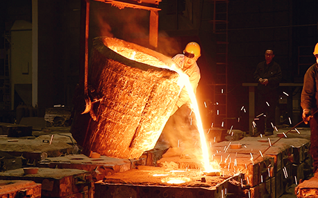
In the forging workshop, industrial furnaces smelt metals, including cupola, induction furnace, resistance furnace, electric arc furnace, vacuum furnace, open hearth furnace, crucible furnace, etc; There are sand mold drying furnace for baking sand mold, ferroalloy drying furnace and casting annealing furnace, etc; In the forging workshop, there are various heating furnaces for heating ingots or billets before forging and heat treatment furnaces for relieving stress after forging;
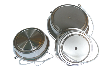
The most effective way for the failure of the medium frequency furnace is to use the low current experiment to judge whether it is the fault of the rectifier circuit or the fault of the inverter part. In the low current experiment, when the DC voltage is less than 513v, it indicates that there is a phase loss fault in the DC rectifier part. Check the specific thyristor fault, and the pulse breaking method should be used to judge whether it is the thyristor fault or there is no trigger pulse.
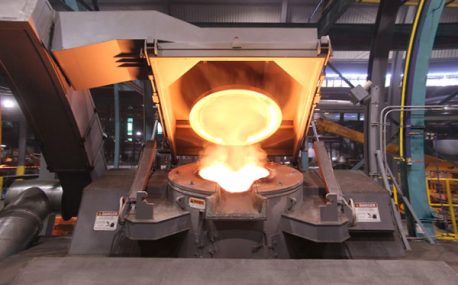
The most effective method for the failure of the intermediate frequency furnace is to use a small current experiment to judge whether the rectifier circuit is faulty or part of the inverter fault. When the DC current is less than 513 volts

Please send us your request and we will reply to you within 24 hours.
We will get in touch with you as soon as possible
