- Tel:+8616638907067
- Email:[email protected]
Induction furnace power supply sizing cannot be completed from furnace tonnage alone. A practical selection must also consider the metal, required hourly output, cold-start melting time, tapping temperature, available transformer capacity, cooling conditions and whether the plant will operate one or several furnaces. A capacity chart can identify a starting range, but it is not excerpt …
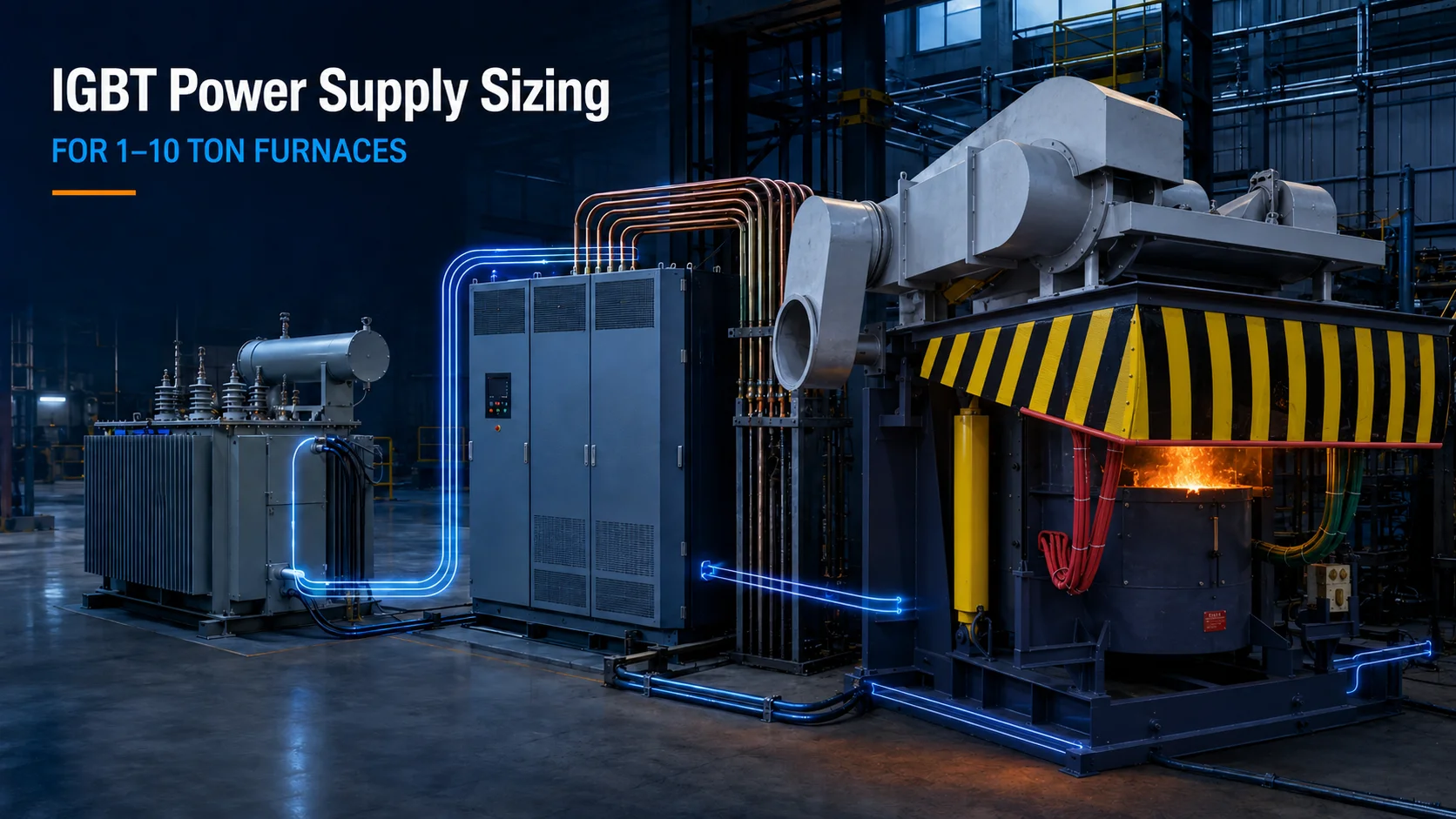
Induction furnace power supply sizing cannot be completed from furnace tonnage alone. A practical selection must also consider the metal, required hourly output, cold-start melting time, tapping temperature, available transformer capacity, cooling conditions and whether the plant will operate one or several furnaces.
A capacity chart can identify a starting range, but it is not a final quotation. Two foundries using the same three-ton furnace may need different power cabinets because their charge materials, production schedules and electrical infrastructure are different.
The first sizing question is not simply, “How many tons is the furnace?” It is, “How many tons of qualified molten metal must the plant produce per hour or per shift?”
A three-ton furnace that completes three heats per shift has a different power requirement from one expected to supply a continuous molding line. Calculate the required melting rate from annual, daily or shift output, then check how much productive melting time is actually available after charging, slag removal, temperature adjustment, tapping and relining downtime.
The RFQ should state batch weight, heats per shift, working hours and target tons per hour. It should also distinguish cold starts from later heats that begin with a hot lining or residual molten metal.
Higher power may shorten the melting stage, but it cannot remove bottlenecks in charging, pouring or material handling. Oversizing the cabinet without checking the rest of the line may increase transformer, switchgear and cooling costs without increasing qualified output. Undersizing creates the opposite risk: longer melting cycles and missed pouring schedules.
Heating solid charge to its melting point, completing the phase change, raising the molten metal to tapping temperature and holding it for pouring are separate energy demands. Steel, cast iron, copper and aluminum therefore should not be assigned the same universal kWh-per-ton figure.
The supplier needs the alloy, initial charge temperature, charge form, target tapping temperature and expected holding time. If molten metal must wait for a slow pouring process, a melt-and-hold arrangement may be more practical than increasing the power of one furnace.
SHENNAI’s technical reference data provides the following basic configuration ranges for medium-frequency IGBT melting systems:
| Circuit configuration | Frequency range | Typical furnace capacity | Power range | Maximum RMS coil voltage |
|---|---|---|---|---|
| Half bridge | 500–1,000 Hz | 0.5–3 tons | 500–2,000 kW | 4 kV |
| Full bridge | 300–500 Hz | 3–10 tons | 2,000–5,000 kW | 5 kV |
These are typical configuration ranges, not automatic model selections. Final matching still depends on the metal, required melting rate, coil parameters and site electrical conditions.
The half-bridge range can be a starting point for smaller furnaces, flexible batch production and applications with moderate output requirements. It does not mean every one-ton furnace needs the same kW rating.
A buyer should confirm the required melting time, actual inverter-module configuration, operating frequency and coil voltage. A three-ton furnace is at the boundary of the half-bridge range, so a high-throughput three-ton project may require a different design from a furnace used for intermittent melting.
For larger furnaces and higher output requirements, a full-bridge IGBT medium-frequency power supply may provide the necessary module and power configuration. SHENNAI’s reference range covers 3–10 tons at 2,000–5,000 kW and 300–500 Hz.
Full bridge should not be selected from tonnage alone. At the three-ton boundary, engineers should compare the target output, cold-start time, load variation and future production plan. Buyers should request confirmation of bridge topology, rated power, module count, frequency range and maximum coil voltage—not only ask whether the cabinet “uses IGBT.”
The furnace transformer must support the input demand of the complete system, not just the nominal furnace capacity. Its review should include rated kVA, primary and secondary voltage, impedance, vector group, rectifier pulse configuration, auxiliary loads and the number of furnaces that may operate simultaneously.
A simple preliminary check can compare required input kW with the expected power factor, but it cannot replace transformer and power-quality engineering. The final design must also account for local switchgear, cables, protection settings and any applicable derating.
For an existing plant, send the transformer nameplate, single-line diagram and operating records to the supplier. A transformer that is too small may experience excessive temperature rise or voltage drop, preventing the IGBT cabinet from maintaining its intended output. A transformer selected with unnecessary excess capacity increases initial cost and may affect utility demand charges.
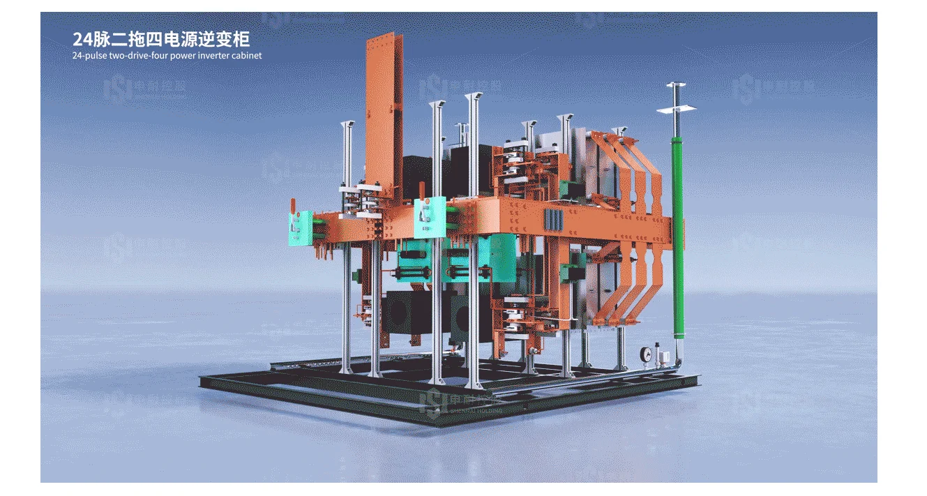
SHENNAI’s system architecture uses a phase-shifting transformer and diode rectification in applicable configurations. Its technical data also describes 12-pulse and 24-pulse arrangements for harmonic control. The suitable arrangement must be checked against the utility connection and the applicable power-quality requirements at the point of common coupling.
Power electronics, compensation capacitors, induction coils and water-cooled cables require stable cooling. The RFQ should state incoming water temperature, flow, pressure, water quality and cooling-system type.
Altitude, ambient temperature, conductive dust and ventilation can also affect available output and component temperature. Ask whether the proposed cabinet requires derating under the stated conditions. Do not apply a generic altitude or temperature correction without a supplier-approved curve for the selected system.
A power cabinet can be arranged around one furnace, a standby furnace, a switched twin-furnace layout or a simultaneous dual-output system. These configurations solve different production problems.
One cabinet with one furnace minimizes equipment count, but furnace maintenance can stop melting. A second standby body improves availability but does not necessarily increase output. A switched system allows two furnaces to alternate, while a properly configured dual-output system may distribute power between melting and holding duties.
“One power supply for two furnaces” does not always mean that both furnaces can receive power simultaneously. The proposal should identify whether the system uses a furnace-change switch, a standby connection or independent inverter outputs.
SHENNAI’s technical architecture includes an one power supply for two induction furnaces option for applicable configurations. Its dual-output documentation describes adjustable power distribution between two furnace bodies, including one furnace melting while the other holds molten metal. Total available transformer and cabinet power still limits combined operation.
Replacing an SCR cabinet with an IGBT cabinet is not always a cabinet-only exchange. The new system must be matched to the existing furnace body, coil and compensation circuit.
Before quoting, the supplier should review furnace capacity, coil inductance and resistance, operating frequency, rated coil voltage, capacitor-bank data, water-cooled cables and bus connections. The existing resonant topology also matters. A cabinet may be able to start the furnace without being correctly matched for continuous rated operation.
SHENNAI’s reference data lists a maximum RMS coil voltage of 4 kV for its typical half-bridge range and 5 kV for the 3–10 ton full-bridge range. Existing coil insulation and capacitor ratings must be checked against the proposed output.
The engineering result may be a cabinet-only replacement, replacement of both the cabinet and capacitor system, coil rematching, or replacement of the complete furnace and power system. Buyers should not assume the lowest-cost option is technically acceptable before these parameters are reviewed.
A compatibility audit should also cover cooling capacity, cabinet footprint, cable routing, grounding, switchgear interlocks, leakage detection, water-temperature protection and the operator control system.
SHENNAI technical data describes overvoltage, overcurrent, maximum-current and maximum-coil-voltage protection, together with monitoring of DC-bus voltage, cooling-water temperature, resonant voltage and fault information. Applicable modular configurations also use independent driver-board control and rapid protection against short circuits or abnormal discharge. These features can reduce the risk of cascading damage, but they do not mean every fault can be isolated without interrupting production.
For a retrofit review, provide equipment nameplates, electrical drawings, coil and capacitor parameters, cooling-system data, fault history and clear photographs.
A useful operating-cost comparison starts with measured production data. Online “industry average” figures are not a reliable substitute for the plant’s electricity meter, qualified output and operating records.
Use the same cost boundary for both the existing and proposed systems. Decide whether kWh per ton includes only the power cabinet or also the cooling tower, hydraulic system and holding losses.
Annual melting energy =
Annual qualified output (tons) × Energy use (kWh/ton)
Annual energy cost =
Annual melting energy × Local electricity tariff
Annual energy saving =
(Baseline kWh/ton − Proposed kWh/ton)
× Annual qualified output × Tariff
Where the utility applies a demand charge, peak billed kW must be calculated separately. A faster furnace may reduce melting time but still create a higher short-term demand peak.
SHENNAI’s technical presentation reports an approximately 3%–5% efficiency improvement compared with the referenced SCR power-supply arrangement. It also reports about 5%–6% shorter melting time under the compared constant-power operating conditions. The same technical comparison lists power factor above 0.98 during the IGBT melting process and conversion efficiency of 98%, compared with 95% for the referenced SCR system.
These figures can support an initial feasibility study, but the quotation should define what is guaranteed for the specific furnace, metal and operating schedule. Shorter melting time does not automatically mean electricity cost falls by the same percentage.
For example, consider a clearly hypothetical project producing 5,000 tons per year. If measured consumption falls from 620 to 600 kWh per ton and electricity costs $0.10/kWh, the calculated annual energy saving is:
(620 − 600) × 5,000 × $0.10 = $10,000 per year
This example excludes demand charges, holding energy, maintenance and production-value gains. Simple payback should use verified total annual savings divided into the net retrofit investment.
A useful induction furnace power supply quotation should be based on:
Metal and alloy grade;
Batch capacity and target tons per hour;
Cold-start melting time and tapping temperature;
Heats per shift and holding requirements;
Local voltage, frequency and transformer nameplate;
Single-, twin- or multi-furnace operation;
Simultaneous power sharing, switching or standby requirements;
Existing coil and capacitor data for retrofit projects;
Cooling-water temperature, flow, pressure and quality;
Altitude, ambient temperature, dust and ventilation;
Required monitoring, protection and spare parts;
Drawings, photographs and installation schedule.
Luoyang Shennai Power Equipment Co., Ltd. can use this information to review the furnace body, IGBT cabinet, transformer and production schedule as one system. A quotation issued without these inputs may identify a nominal model, but it cannot reliably confirm output, compatibility or operating cost.
Treat furnace tonnage as a capacity limit, not as a power rating. Start with the metal, hourly output and cold-start time; use the SHENNAI configuration range for initial screening; then verify the transformer, cooling system, operating mode and retrofit interfaces.
For a project-specific review, submit your furnace data for an engineering quotation, including the transformer nameplate, production target, operating schedule and existing-equipment information. This allows the proposed power cabinet to be evaluated against real production and site conditions rather than tonnage alone.
There is no universal rating. SHENNAI’s typical half-bridge range covers 0.5–3 tons and 500–2,000 kW, but the actual one-ton selection depends on metal, hourly output and cold-start time.
Not necessarily. Three tons is the boundary between SHENNAI’s typical half-bridge and full-bridge ranges. Target power, frequency, production schedule and future expansion should determine the final topology.
Possibly, after checking rated kVA, secondary voltage, impedance, vector group, pulse configuration, cooling and simultaneous loads. A nameplate alone may not provide enough information.
Yes, with an appropriate configuration. The system may use switching, standby connection or simultaneous dual outputs. The quotation must identify which method is included and how total power is distributed.
Use measured or contractually defined kWh per ton, qualified annual output, the local energy tariff and any demand charges. Keep auxiliary and holding loads consistent when comparing existing and proposed systems.
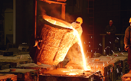
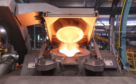
In the forging workshop, industrial furnaces smelt metals, including cupola, induction furnace, resistance furnace, electric arc furnace, vacuum furnace, open hearth furnace, crucible furnace, etc; There are sand mold drying furnace for baking sand mold, ferroalloy drying furnace and casting annealing furnace, etc; In the forging workshop, there are various heating furnaces for heating ingots or billets before forging and heat treatment furnaces for relieving stress after forging;
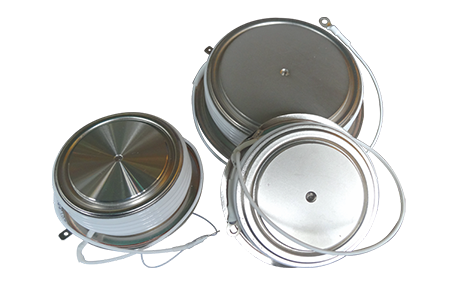
The most effective way for the failure of the medium frequency furnace is to use the low current experiment to judge whether it is the fault of the rectifier circuit or the fault of the inverter part. In the low current experiment, when the DC voltage is less than 513v, it indicates that there is a phase loss fault in the DC rectifier part. Check the specific thyristor fault, and the pulse breaking method should be used to judge whether it is the thyristor fault or there is no trigger pulse.
The most effective method for the failure of the intermediate frequency furnace is to use a small current experiment to judge whether the rectifier circuit is faulty or part of the inverter fault. When the DC current is less than 513 volts

Please send us your request and we will reply to you within 24 hours.
We will get in touch with you as soon as possible
