- Tel:+8616638907067
- Email:[email protected]
There is no universal winner in an SCR vs IGBT induction furnace comparison. IGBT is often worth closer evaluation when a foundry needs responsive power regulation, stable output as the furnace load changes, flexible part-load operation, and modular fault management. SCR can remain a practical option for large-capacity or higher-voltage systems, plants with mature thyristor excerpt …
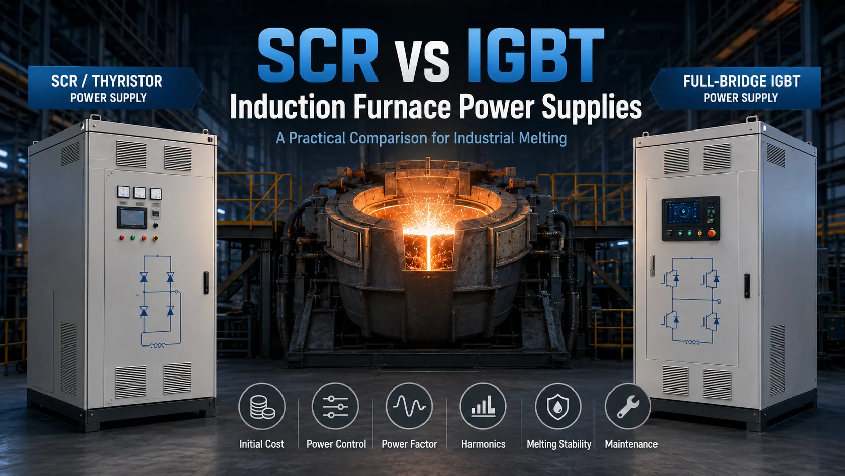
There is no universal winner in an SCR vs IGBT induction furnace comparison. IGBT is often worth closer evaluation when a foundry needs responsive power regulation, stable output as the furnace load changes, flexible part-load operation, and modular fault management. SCR can remain a practical option for large-capacity or higher-voltage systems, plants with mature thyristor maintenance resources, and projects where existing infrastructure or initial investment strongly affects the decision.
The correct comparison is not simply “thyristor versus transistor.” Buyers must compare the complete rectifier and inverter topology, furnace capacity, incoming voltage, resonant circuit, control method, cooling system, fault protection, production duty, and total cost of ownership.
An SCR power supply may fit a project where the foundry already has compatible transformers, coils, capacitors, spare parts, and technicians familiar with thyristor systems. Modern SCR systems can also use series-resonant, multi-pulse, or multi-furnace configurations, so SCR should not automatically be treated as an obsolete, low-power-factor technology.
IGBT deserves stronger consideration when production involves frequent load changes, different alloys, shorter batch cycles, regular part-load operation, or a need for faster electronic control. IGBTs combine high current and blocking-voltage capability with fast, gate-controlled switching, but those device-level characteristics only become useful furnace performance when the driver, resonant circuit, cooling, sensing, and protection systems are correctly engineered.
| Comparison factor | SCR power supply | Full-bridge IGBT power supply | What the buyer should verify |
|---|---|---|---|
| Initial investment | May be favorable when compatible infrastructure already exists | Control and module costs may be higher | Compare identical power, furnace, cooling, and service scope |
| Power regulation | Strongly dependent on series or parallel topology | Faster active switching supports flexible regulation | Request a full-heat output curve |
| Part-load operation | Varies considerably by topology and control method | Often a key reason to evaluate IGBT | Compare active power and PF at several load points |
| Constant-power behavior | Available in some modern SCR series systems | Can be designed for near-constant output | Confirm voltage and current limiting regions |
| Power factor | Not universally low | Not automatically unity | Define load, meter location, and PF type |
| Harmonics | Influenced by pulse count, transformer, and filtering | Influenced by rectifier and complete architecture | Request THDi and THDv at the agreed connection point |
| Large-capacity use | Relevant in many high-power configurations | Depends on available voltage and module configuration | Confirm supplier-specific limits |
| Failure behavior | Depends on thyristors, fuses, protection, and commutation | Depends on modules, drivers, protection, and fault isolation | Ask what one device failure disables |
| Retrofit complexity | Existing equipment may remain compatible | Transformer, coil, capacitor, or cooling changes may be required | Complete a compatibility study |
| Maintenance | May suit plants with mature local SCR experience | Can support module-level diagnosis and replacement | Confirm spare-part availability and replacement procedure |
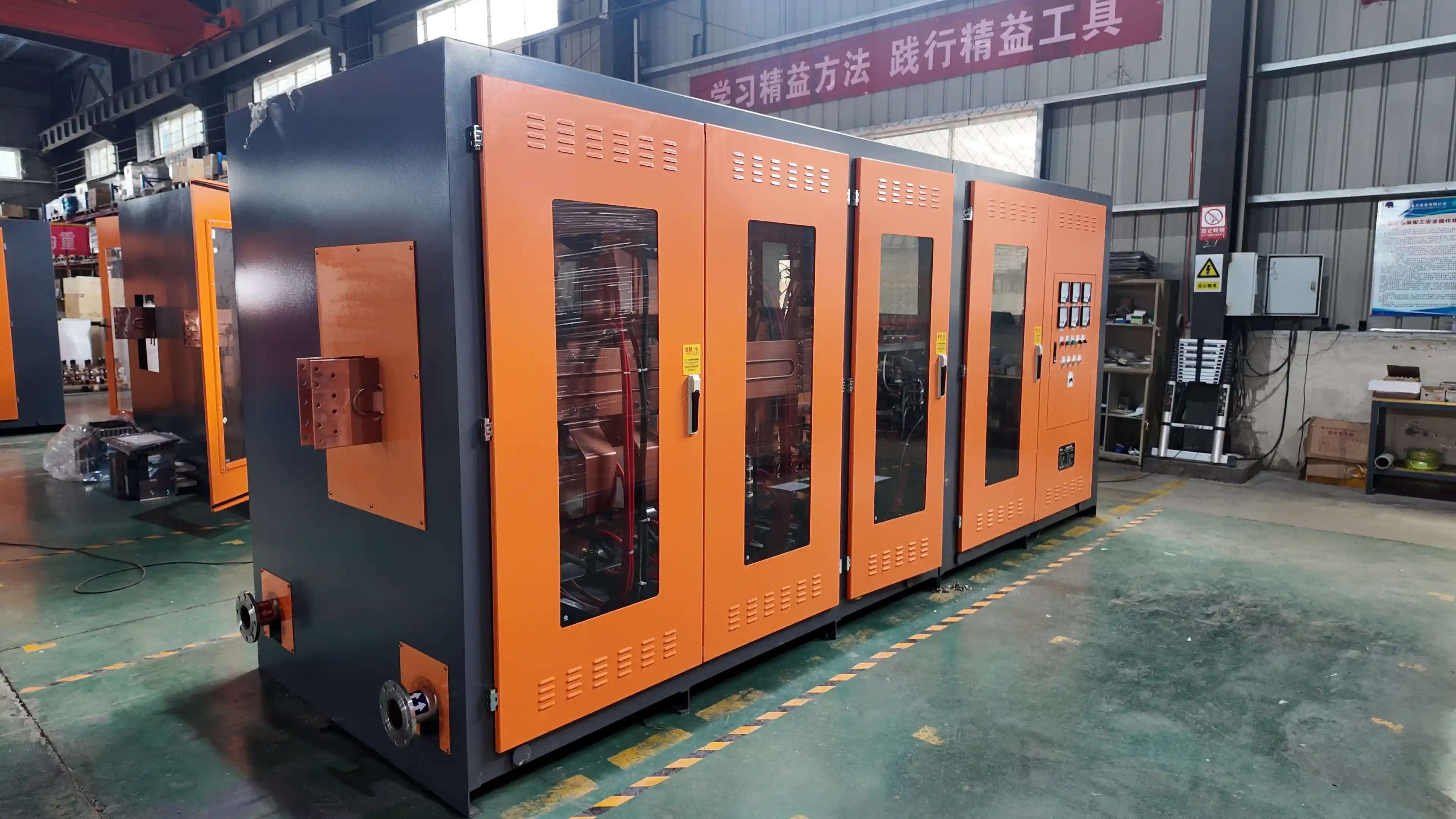
“SCR induction furnace” describes the semiconductor family, not a single electrical architecture. A traditional parallel inverter, a modern series inverter, and a multi-pulse thyristor power supply can have significantly different control behavior and project applications.
The rectifier pulse number, transformer connections, DC-link design, resonant circuit, filtering, and control algorithm all affect power factor, harmonic current, load matching, and output stability. A supplier that only writes “SCR” in a quotation has not provided enough information for a meaningful comparison.
In SHENNAI’s current technical range, the listed series-connected medium-frequency power supplies cover 380–1,000 V input and furnace capacities from 0.5 to 30 metric tons, with an applicable stated power-factor range of 0.95–0.98. The listed parallel configurations cover 380–1,650 V and 0.1 to 60 metric tons. These are SHENNAI configuration boundaries, not universal industry limits.
SCR operation also differs fundamentally from IGBT operation. An SCR is triggered into conduction and remains latched until the current falls below the required holding condition; its stored charge must then recover before it can block voltage again. STMicroelectronics describes standard SCRs as devices intended for relatively low-frequency switching and explains their latching and recovery behavior.
An IGBT can be actively switched on and off through its gate. This allows faster control action than a conventional thyristor, but the semiconductor alone does not create constant power or low harmonics.
A complete full-bridge IGBT medium-frequency power supply also requires:
A correctly selected rectifier and DC link
A matched induction coil and capacitor circuit
Resonant-frequency control
Current and voltage feedback
Gate-driver coordination
Cooling and interlocks
Short-circuit, overvoltage, and discharge protection
SHENNAI’s current IGBT technical range is stated as 6–24 pulse, 380–660 V input, and furnace capacities from 0.1 to 10 metric tons. The system uses a capacitor-coil series-resonant circuit with phase-shifted, phase-locked power regulation. These limits apply to the described configurations and should be reconfirmed for each project.
A technically useful quotation comparison should calculate:
Total Cost of Ownership=CAPEX+electricity+spare parts+maintenance+downtime+retrofit work\text{Total Cost of Ownership} = \text{CAPEX} +\text{electricity} +\text{spare parts} +\text{maintenance} +\text{downtime} +\text{retrofit work}Total Cost of Ownership=CAPEX+electricity+spare parts+maintenance+downtime+retrofit work
A lower initial price may be attractive when the plant has modest annual production, established SCR maintenance capability, and compatible equipment. A higher initial price may be justified when stable production, reduced melt-cycle variation, easier fault diagnosis, or electricity savings have greater financial value.
The calculation should use the plant’s own information:
Annual tapped tonnage
Measured kWh per ton
Local electricity tariff
Average melt and holding times
Production loss per hour of downtime
Expected spare-parts inventory
Planned operating life
A continuous foundry supplying an automated molding or casting line will value downtime differently from a small plant operating several heats per week. No credible supplier can provide a universal payback period without these inputs.
The electrical load changes throughout a heat. Cold charge, charge collapse, formation of the liquid bath, superheating, and holding do not present the same impedance to the power supply.
Buyers should request a logged full-heat curve showing:
Active input and output power
Current and voltage limits
Power factor
Time near rated power
Power reductions during charge collapse
Trips or restart periods
Holding duration
SHENNAI’s IGBT design uses series resonance and phase-shifted regulation to support stable or near-constant power as applicable load conditions change. According to SHENNAI technical data, its described IGBT configuration maintains a power factor of at least 0.97 under applicable system conditions. The same data reports approximately 3%–5% lower energy use than the referenced traditional thyristor arrangement under comparable operating conditions.
That percentage is not a general promise for every retrofit. A valid comparison must use the same metal, net tapped weight, furnace capacity, charge condition, tapping temperature, holding time, measurement boundary, and auxiliary loads.
Power factor claims are frequently misleading because suppliers may report different measurements. Total power factor includes the effect of harmonic currents, while displacement power factor describes the phase relationship of the fundamental-frequency components. Schneider Electric specifically distinguishes total PF from cos φ and explains how harmonic current affects the relationship between them.
Ask every supplier to state:
Whether the figure is total PF or displacement PF
The load percentage at which it was measured
Whether measurement was taken at the inverter, transformer, or point of common coupling
Current and voltage THD
Rectifier pulse count
Transformer phase-shift arrangement
Installed filters or reactors
IGBT does not automatically mean lower incoming harmonics, and SCR does not automatically mean poor power factor. The complete front-end and system design determine the result.
Do not compare systems only by rated kilowatts. A 2,000 kW cabinet that spends much of the heat at 1,300 kW may deliver a slower and less efficient cycle than a correctly matched lower-rated system that remains close to its usable output.
For comparable heats, record:
Average active power
Percentage of melting time above 90% of rated power
Time spent at current or voltage limits
Power dips during charge collapse
Protection events
Melting and holding time
kWh per net tapped ton
This analysis helps determine whether the restriction comes from power-supply regulation, transformer voltage, resonant matching, furnace lining, coil condition, cooling capacity, or operating practice.
SCR may deserve priority evaluation when the project involves a large furnace, higher input voltage, an existing thyristor installation, established local repair expertise, or a requirement to preserve compatible transformers and furnace equipment.
IGBT may deserve priority evaluation when the plant frequently changes charge conditions, operates at different power levels, needs tighter cycle control, or wants modular electronic diagnostics. It can also be suitable for smaller or flexible batch operations where compact equipment and responsive control are important.
Furnace structure remains a separate decision. A steel shell induction furnace for continuous melting may be selected for rigidity and demanding production, while an aluminum shell induction furnace for flexible batch production may suit smaller or less intensive applications. Either furnace type still requires a properly matched power supply; the shell material does not determine whether SCR or IGBT is automatically correct.
Multi-furnace systems add another layer. SHENNAI documents one-to-two and one-to-multiple thyristor configurations with independent furnace power regulation. A buyer should compare furnace switching, power sharing, holding capability, transformer use, and what happens when one furnace is isolated for maintenance.
Both SCR and IGBT equipment can be damaged by inadequate cooling, short circuits, furnace arcing, overvoltage, loose connections, incorrect load matching, or control faults. The semiconductor label alone does not establish reliability.
A quotation should explain:
What detects overcurrent or short circuit
How quickly the system removes gate signals
How fuses and electronic protection coordinate
How overvoltage is limited
Which cooling conditions trigger shutdown
What fault data are logged
Which parts require inspection after an event
What conditions permit restart
SCRs have device characteristics that can make them robust in appropriate low-frequency, high-power applications, including immunity to surges and transients when correctly selected and operated. That does not remove the need for suitable commutation, cooling, and protection design.
SHENNAI’s described IGBT system uses independently controlled drive modules rather than one shared drive arrangement for an entire device group. Its protection design is intended to respond quickly to furnace short circuits and arcing discharges, reducing the risk that one abnormal event causes cascading damage across multiple devices.
For buyers, the practical questions are:
Can the controller identify the failed module?
Can a local technician replace the driver or power module?
What programming or calibration is required afterward?
Which modules, drivers, fuses, fiber-optic parts, and sensors should be kept on-site?
Does any proposed reduced-power operation apply to this specific configuration?
What remote support is available during an overseas failure?
Modular design does not mean that the furnace can continue operating after every fault. The supplier must define which faults can be isolated and which require a full shutdown and inspection.
An SCR-to-IGBT upgrade is not simply a cabinet replacement. Before comparing prices, provide the supplier with:
Transformer primary and secondary voltage
Transformer kVA
Existing rectifier pulse arrangement
Furnace capacity and rated power
Coil inductance and operating current
Capacitor-bank data
Operating frequency
Busbar and water-cooled cable ratings
Cooling-water flow, pressure, and temperatures
Control interfaces
Installation dimensions
Grounding and protection information
Single-, dual-, or multi-furnace operating mode
The existing coil, capacitor bank, and transformer may not match the proposed IGBT resonant circuit. The cooling system may also be insufficient for the new cabinet and operating duty. A preliminary engineering review should identify which equipment can remain, which must be modified, and which must be replaced.
Keeping the existing SCR system may be more economical when its output, power factor, energy consumption, and reliability are already acceptable; when the main problem is poor charge preparation or long holding time; or when an upgrade would require replacing most of the electrical and cooling infrastructure.
Ask every bidder to provide equivalent evidence rather than comparing marketing labels.
A useful RFQ should request:
Complete power-supply topology
Continuous and maximum output ratings
Input voltage and transformer requirements
Full-heat power curve
PF over the specified load range
THDi and THDv measurement conditions
Cooling requirements
Protection sequence
Fault and alarm list
Semiconductor replacement procedure
Recommended spare-parts package
Energy-consumption test conditions
Retrofit inclusions and exclusions
Commissioning and training scope
For a preliminary SHENNAI assessment, submit the metal, furnace capacity, target tons per hour, existing SCR or IGBT type, rated power, input voltage, transformer nameplate, coil and capacitor information, melt time, kWh per ton, PF or harmonic report, cooling conditions, and fault history.
Reviewing SHENNAI induction melting system capabilities can help project teams determine which technical documents and site data are needed before requesting a final configuration.
SCR can remain suitable for established, high-capacity, high-voltage, or investment-sensitive projects. IGBT can offer valuable control and maintenance advantages where the load changes frequently and production stability is important.
The decision should compare the full topology, power curve, grid performance, retrofit requirements, spare-parts strategy, and total cost of ownership. Project teams can review industrial induction melting furnace systems or submit their SCR or IGBT power-supply requirements for a preliminary configuration assessment.
No. IGBT may offer faster control and flexible regulation, while an SCR series or parallel system may better fit certain high-capacity, high-voltage, existing-infrastructure, or budget-sensitive projects. The complete system and operating duty determine suitability.
No. Older parallel inverter designs and modern multi-pulse or series-resonant SCR systems should not be treated as identical. Current thyristor systems can remain relevant where their capacity, voltage, control, and maintenance characteristics match the project.
Possibly, but the transformer, coil, capacitor bank, operating frequency, cooling system, busbars, controls, and protection must be checked first. Some projects require more than replacing the power cabinet.
It depends on local technician experience, spare-part availability, diagnostic functions, module design, documentation, and remote support. A familiar SCR system may be easier locally, while a modular IGBT system may simplify fault identification when appropriate spares are available.
No. Power factor depends on the complete topology and load range. Some modern SCR series systems can also provide a high power factor. Quotations should identify total PF, displacement PF, load percentage, and measurement location.
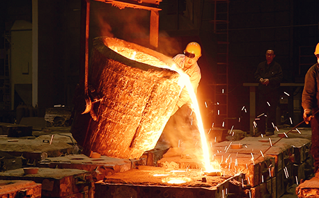
In the forging workshop, industrial furnaces smelt metals, including cupola, induction furnace, resistance furnace, electric arc furnace, vacuum furnace, open hearth furnace, crucible furnace, etc; There are sand mold drying furnace for baking sand mold, ferroalloy drying furnace and casting annealing furnace, etc; In the forging workshop, there are various heating furnaces for heating ingots or billets before forging and heat treatment furnaces for relieving stress after forging;
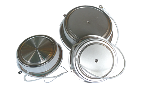
The most effective way for the failure of the medium frequency furnace is to use the low current experiment to judge whether it is the fault of the rectifier circuit or the fault of the inverter part. In the low current experiment, when the DC voltage is less than 513v, it indicates that there is a phase loss fault in the DC rectifier part. Check the specific thyristor fault, and the pulse breaking method should be used to judge whether it is the thyristor fault or there is no trigger pulse.
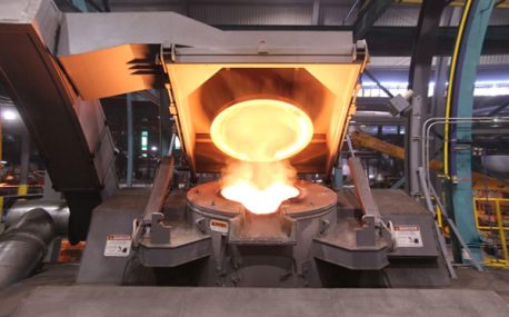
The most effective method for the failure of the intermediate frequency furnace is to use a small current experiment to judge whether the rectifier circuit is faulty or part of the inverter fault. When the DC current is less than 513 volts

Please send us your request and we will reply to you within 24 hours.
We will get in touch with you as soon as possible
