- Tel:+8616638907067
- Email:[email protected]
A practical reference for induction furnace energy consumption per ton is approximately 530–600 kWh per metric ton when melting steel. For a well-operated modern iron batch melter, about 500–530 kWh per ton can be used as a best-practice planning reference. These figures are not universal performance guarantees: metal grade, tapping temperature, charge condition, furnace utilization, holding time, excerpt …
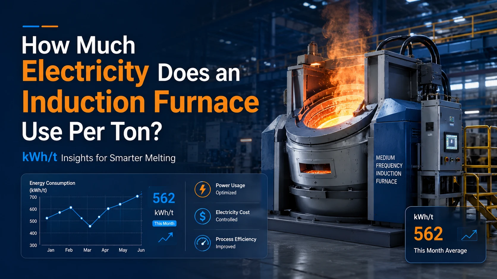
A practical reference for induction furnace energy consumption per ton is approximately 530–600 kWh per metric ton when melting steel. For a well-operated modern iron batch melter, about 500–530 kWh per ton can be used as a best-practice planning reference. These figures are not universal performance guarantees: metal grade, tapping temperature, charge condition, furnace utilization, holding time, lining condition, and the measurement boundary can move the actual result considerably. The U.S. Department of Energy also notes that its 530 kWh/t iron example covers melt energy and excludes cooling-water pumps and heat exchangers.
The most reliable calculation is simple:
kWh per ton=electricity used during the batch in kWhnet tapped metal in metric tons\text{kWh per ton}= \frac{\text{electricity used during the batch in kWh}} {\text{net tapped metal in metric tons}}kWh per ton=net tapped metal in metric tonselectricity used during the batch in kWh
Rated furnace power in kilowatts does not tell you the electricity consumed per ton. A 1,500 kW furnace running efficiently for a short cycle may use less energy per ton than a 1,000 kW furnace that spends longer at reduced power or waits with molten metal in the crucible.
A benchmark is useful for feasibility studies, supplier comparisons, and identifying abnormal operation. It should not be treated as a contractual consumption value unless the metal, charge mix, tapping temperature, production pattern, measurement method, and auxiliary loads are defined.
The DOE’s historical analysis gives two useful reference points:
Steel normally requires a higher tapping temperature than cast iron, which is one reason the two processes should not be compared without checking the actual metallurgical specification.
A plant should therefore maintain three separate numbers:
The third number is the one that should guide maintenance, process improvement, or replacement decisions.
Two suppliers may quote different energy figures while both are technically correct because they are measuring different loads.
A power-supply-only measurement may exclude the cooling pumps, cooling tower, hydraulic station, dust extraction, and holding furnace. A melting-cell measurement may include the furnace power supply and cooling system. A plant-level figure may also include delays, auxiliary equipment, and other production loads.
The denominator also matters. Use net tapped liquid metal, not gross charge weight. Rust, slag, dross, spilled metal, residual heel, and process losses mean that one ton of charge is not necessarily one ton of useful molten metal.
Cold-start heats should be separated from continuous hot-furnace production. Likewise, a batch that waits 25 minutes for a ladle or molding line should not be compared directly with a batch tapped immediately after reaching temperature.
Record the meter immediately before starting the heat and again after tapping:
Ebatch=final meter reading−initial meter readingE_{\text{batch}}= \text{final meter reading}-\text{initial meter reading}Ebatch=final meter reading−initial meter reading
Then calculate:
Specific energy consumption=Ebatchnet tapped weight\text{Specific energy consumption}= \frac{E_{\text{batch}}} {\text{net tapped weight}}Specific energy consumption=net tapped weightEbatch
For useful production analysis, record at least the following for each heat:
A single heat can be misleading. Record a series of comparable heats and examine the average, median, and outliers. This helps distinguish a persistent equipment problem from an isolated delay or unusual charge.
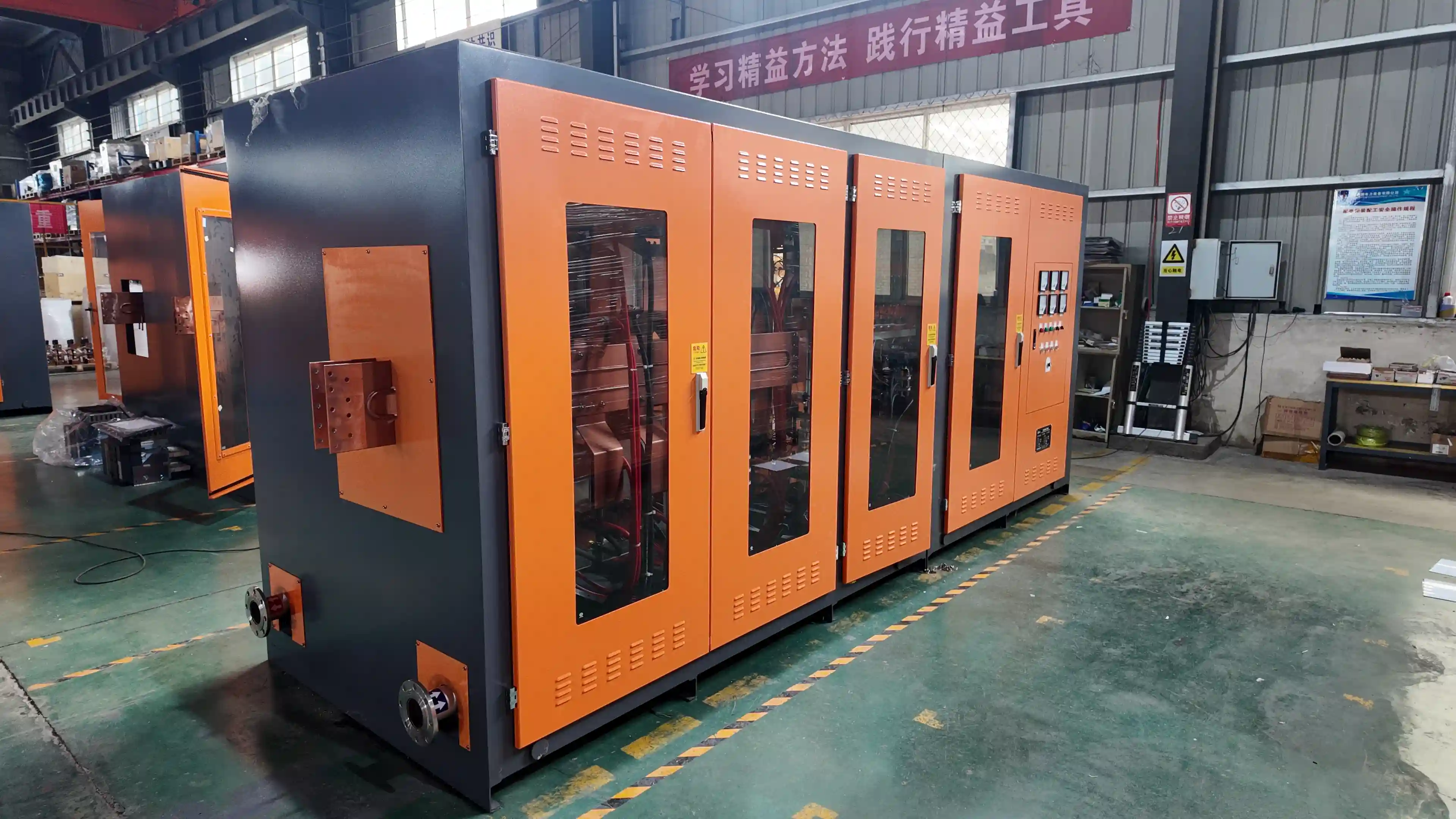
When an integrated energy meter is unavailable, active input power in a balanced three-phase system can be estimated as:
P(kW)=3×V×I×PF1000P(\text{kW})= \frac{\sqrt{3}\times V\times I\times PF}{1000}P(kW)=10003×V×I×PF
Energy is then:
E(kWh)=Paverage×tE(\text{kWh})=P_{\text{average}}\times tE(kWh)=Paverage×t
Schneider Electric uses the same relationship for three-phase active power, based on average RMS voltage, average RMS current, and power factor.
This method is suitable for a preliminary assessment, but it has limitations. Current and power factor change as the charge heats, collapses, melts, and becomes a liquid bath. One control-panel reading cannot represent the full batch. For troubleshooting, use averaged or logged values from a power analyzer rather than multiplying one instantaneous current reading by the entire melting time.
SHENNAI technical tables pair furnace capacity with rated power, voltage, current, frequency, power factor, and reference melting time. These parameters help engineers screen medium-frequency power-supply configurations, but they remain configuration references rather than guaranteed kWh-per-ton values.
Consider a hypothetical furnace heat with:
The batch used:
13,350−12,450=900 kWh13{,}350-12{,}450=900\text{ kWh}13,350−12,450=900 kWh
Specific energy consumption was:
900÷1.5=600 kWh/t900\div1.5=600\text{ kWh/t}900÷1.5=600 kWh/t
The energy charge was:
600×$0.10=$60 per ton600\times\$0.10=\$60\text{ per ton}600×$0.10=$60 per ton
This is only the energy component. The final electricity cost may also include maximum-demand charges, time-of-use rates, power-factor penalties, and auxiliary-system consumption.
Metal type affects the energy needed to reach the required tapping condition. Melting temperature, tapping temperature, alloying practice, slag generation, and required superheat all influence the final result.
Charge preparation is equally important. Dense, correctly sized pieces establish better coupling and reduce the time spent heating an incomplete or loosely packed charge. Very light scrap, inconsistent piece sizes, heavy rust, oil, sand, and coatings can increase processing time, slag, and metal loss.
Moisture is not merely an efficiency concern. The UK Health and Safety Executive warns that water contamination of molten metal can cause explosions and identifies wet scrap as a common source of water entering a furnace. Charge material must be dry and managed under the plant’s approved molten-metal safety procedures.
Preheating can reduce melting demand when it is correctly engineered. DOE best-practice work reported a 50–70 kWh/t reduction in steel-foundry melting energy in the projects it reviewed, but the result depends on the preheating method, heat source, scrap condition, and plant arrangement. It should not be transferred automatically to every foundry.
Heating metal above the required tapping temperature consumes extra electricity and increases heat loss from the bath, lining, and furnace opening. The process team should define a permitted tapping-temperature window rather than relying on a broad operator target.
Holding time should be measured separately from melting time. Common causes include:
Increasing rated power will not solve these delays. The correct action is to coordinate melting completion with the time at which the metal can actually be tapped and poured.
Open-bath time also matters. DOE research identifies radiation from exposed molten-metal surfaces as an important furnace loss and notes that opening a lid or door increases radiation loss.
Lining condition affects both safety and electromagnetic coupling. An unnecessarily thick lining increases the distance between the coil and metal. Uneven wear, localized repairs, or a changing internal profile can also alter the effective load seen by the power supply. Reducing lining thickness without respecting the approved refractory design is not an acceptable energy-saving measure.
The coil should be inspected for deformation, movement, inconsistent turn spacing, damaged insulation, and connection heating. The magnetic yoke should also be checked for looseness, damage, and abnormal local heating. In a steel shell furnace, the yoke helps control magnetic leakage around the coil. SHENNAI’s current steel-furnace design data describes silicon-steel magnetic yokes, flat-wound coils, integral coil casting, and integrated conductive and cooling-water windings. These features are relevant because furnace-body rigidity, magnetic control, and coil geometry all affect the system’s ability to transfer power consistently.
The selection of steel shell induction furnace design should therefore consider operating intensity, furnace capacity, rigidity, access for lining maintenance, magnetic shielding, and the matched power supply—not shell material alone.
Cooling conditions can limit usable output even when the power cabinet is electrically capable of more. Record inlet temperature, outlet temperature, flow, pressure, scaling, and alarm history. Reducing cooling flow to save auxiliary power can overheat the coil or power electronics and should not be used as an efficiency shortcut.
A useful operating indicator is:
Average power utilization=average active kW during meltingrated power\text{Average power utilization}= \frac{\text{average active kW during melting}} {\text{rated power}}Average power utilization=rated poweraverage active kW during melting
This is not the same as thermal efficiency. It shows how much of the available power is being used during the active melting period.
When utilization is low, ask:
A larger transformer or higher-rated cabinet is not automatically the answer. The bottleneck may be the resonant match, furnace body, cooling system, incoming network, or production practice.
| Observed condition | Likely cost layer | What to verify | Possible action |
| Large variation between similar heats | Process | Charge mix, tapping temperature, holding and delay | Standardize charging and production timing |
| Long melt time with low average active power | Power utilization | kW trend, voltage, current, PF and alarms | Check load matching and power-supply control |
| Consumption rises during the lining campaign | Furnace body | Lining profile, coil position and yoke condition | Inspect geometry and mechanical condition |
| Cooling alarms appear at high power | Utilities | Water flow, inlet temperature, pressure and scaling | Correct cooling capacity or blockage |
| Normal kWh/t but high monthly bill | Plant energy | Demand peak, tariff periods and multi-furnace overlap | Review scheduling and energy management |
This separation prevents a common purchasing mistake: replacing the power supply when the dominant loss is extended holding, or rebuilding the furnace when unstable electrical output is the main restriction.
During a heat, the electrical load changes as cold metal warms, the charge collapses, liquid metal forms, and lining conditions vary. A power supply that cannot maintain useful output through these changes may extend the melt cycle and increase time-dependent losses.
SHENNAI’s current technical data describes an IGBT medium-frequency architecture using a capacitor-coil series-resonant circuit with phase-shifted, phase-locked power regulation. Its purpose is to maintain stable or constant power as load conditions change. For applicable configurations, the technical data specifies a power factor of at least 0.97. It also reports approximately 3%–5% lower energy consumption than the compared traditional thyristor arrangement under the stated operating conditions. These figures require equivalent metal, capacity, tapping temperature, cycle boundary, and measurement method before they can be used in a commercial comparison.
For a buyer, the relevant questions are not simply “Is it IGBT?” but:
A reduction in kWh/t normally lowers the energy component of the bill, but it may not address the plant’s full electricity cost.
A demand charge is based on the customer’s maximum capacity usage under the applicable tariff. Two furnaces ramping to high power at the same time can therefore increase the bill even if each furnace has an acceptable kWh-per-ton result.
Review three cost layers:
The tariff must be checked with the local utility. Peak periods, billing intervals, penalties, and demand-calculation methods vary by location.
Plant-level coordination becomes more valuable when a foundry operates multiple furnaces, faces strong peak/off-peak price differences, has limited transformer capacity, or intends to integrate photovoltaic generation and battery storage.
SHENNAI’s ZCIM concept coordinates grid supply, PV, storage, AC and DC buses, and induction-furnace loads. At this layer, the objective is to decide when each load should run and how available energy sources should be allocated. Multi-furnace power control can also coordinate melting, holding, and furnace changeover rather than allowing every unit to reach maximum demand simultaneously.
ZCIM should not be presented as changing the theoretical heat required to melt one ton of metal. Its main cost opportunity is scheduling: reducing demand peaks, using lower-tariff periods, coordinating furnace loads, and using PV or stored energy when the system has been correctly sized. Results depend on the production schedule, utility tariff, grid conditions, battery capacity, state-of-charge limits, conversion topology, and protection design.
A supplier cannot produce a defensible consumption estimate from furnace capacity alone. Prepare one complete data set containing:
From these inputs, SHENNAI can screen the measured kWh/t, average power utilization, possible process losses, power-supply matching, furnace-body inspection priorities, and whether plant-level scheduling deserves further study. This is a preliminary assessment; final equipment selection still requires the metallurgical process, site electrical conditions, cooling design, production target, and installation layout.
Readers can review SHENNAI induction melting system capabilities before submitting technical data.
Induction furnace electricity cost should be analyzed in three layers. First, control charge condition, tapping temperature, holding, and production delays. Second, inspect the lining, coil, yoke, cooling system, and power-supply utilization. Third, examine demand peaks, tariff periods, and multi-furnace scheduling.
A steel-melting reference of roughly 530–600 kWh/t is useful for initial planning, but the plant’s own batch meter and net tapped weight provide the decision-grade number.
For a project-specific review, examine SHENNAI’s industrial induction melting furnace systems or submit your furnace operating data for a preliminary assessment. Include the metal, capacity, net tapped weight, batch kWh, melting and holding time, voltage, current, power factor, transformer capacity, cooling conditions, and tariff structure.
No. A correctly matched higher-power furnace may complete the heat faster and reduce time-dependent heat loss. However, excess rated power provides little benefit when the transformer, coil, cooling system, charge practice, or downstream production cannot support it.
It depends on the measurement boundary. State clearly whether the figure covers only the power cabinet or also includes pumps, cooling towers, hydraulics, dust extraction, and holding equipment. Use the same boundary when comparing alternatives.
Shell material alone does not determine energy consumption. Compare the magnetic-yoke arrangement, coil geometry, lining thickness, furnace capacity, structural rigidity, production intensity, cooling system, and matched power supply.
It may reduce avoidable waiting and improve load coordination, but its primary role is plant-level energy-cost control. Peak-demand reduction, tariff scheduling, PV use, and storage dispatch do not necessarily change the basic thermal energy required by the metal.
As a practical starting point, record 10–20 comparable heats. Keep the metal, tapping-temperature range, charge practice, and measurement boundary consistent, and mark heats affected by trips, long holding periods, or production delays.
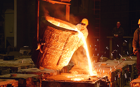
In the forging workshop, industrial furnaces smelt metals, including cupola, induction furnace, resistance furnace, electric arc furnace, vacuum furnace, open hearth furnace, crucible furnace, etc; There are sand mold drying furnace for baking sand mold, ferroalloy drying furnace and casting annealing furnace, etc; In the forging workshop, there are various heating furnaces for heating ingots or billets before forging and heat treatment furnaces for relieving stress after forging;
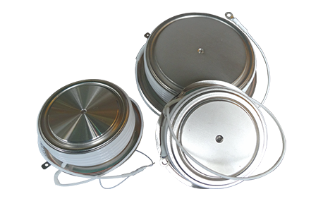
The most effective way for the failure of the medium frequency furnace is to use the low current experiment to judge whether it is the fault of the rectifier circuit or the fault of the inverter part. In the low current experiment, when the DC voltage is less than 513v, it indicates that there is a phase loss fault in the DC rectifier part. Check the specific thyristor fault, and the pulse breaking method should be used to judge whether it is the thyristor fault or there is no trigger pulse.
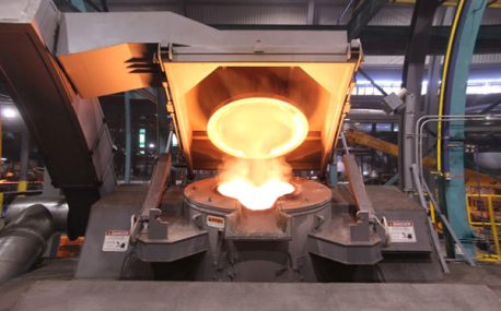
The most effective method for the failure of the intermediate frequency furnace is to use a small current experiment to judge whether the rectifier circuit is faulty or part of the inverter fault. When the DC current is less than 513 volts

Please send us your request and we will reply to you within 24 hours.
We will get in touch with you as soon as possible
