- Tel:+8616638907067
- Email:[email protected]
Battery energy storage for foundries can reduce short, recurring demand peaks, shift electricity use between tariff periods, absorb surplus photovoltaic generation, and support selected loads during brief power disturbances. However, a battery energy storage system, or BESS, cannot be sized from furnace tonnage or nameplate power alone. The engineering decision depends on the actual load excerpt …
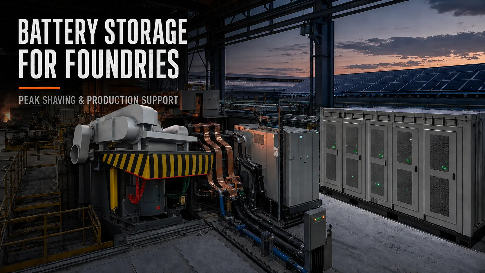
Battery energy storage for foundries can reduce short, recurring demand peaks, shift electricity use between tariff periods, absorb surplus photovoltaic generation, and support selected loads during brief power disturbances. However, a battery energy storage system, or BESS, cannot be sized from furnace tonnage or nameplate power alone.
The engineering decision depends on the actual load profile, peak duration, transformer limit, electricity tariff, furnace schedule, PV output, and required backup boundary. A system designed for foundry peak shaving is also not automatically capable of powering a complete induction furnace during a grid outage.
An induction furnace does not draw the same power throughout every heat. Demand changes during a cold start, initial charging, scrap settling, melting, temperature raising, holding, and tapping. Changes in charge density, metal condition, and furnace lining can also alter the electrical load seen by the power supply.
For this reason, rated furnace power only indicates an upper design value. It does not show how long that power is required or when it overlaps with other equipment. A useful feasibility study must identify actual input power during each production stage, the length of those stages, and the difference between cold-furnace and hot-furnace operation.
Holding, cooling, dust extraction, charging equipment, air compressors, and other auxiliaries must also be included. A battery selected from furnace power alone may be oversized for a short peak or undersized for a sustained production cycle.
In a multi-furnace foundry, the highest electrical demand may occur when one furnace is holding metal while another starts a cold charge. Cooling towers, pumps, dust collectors, and compressed-air systems can add further load at the same time.
Before purchasing an industrial battery storage system, the plant should determine whether its peak can first be reduced through scheduling. Delaying the second furnace start, separating high-load auxiliary operations, or controlling battery recharge may reduce the required BESS power.
Production constraints still come first. A lower electrical peak is not useful if it disrupts tapping temperature, casting timing, lining practice, or cooling safety. The objective is to coordinate the production schedule and energy system, not simply cap power without considering the melting process.
“Reduce electricity cost” is not a sufficiently precise design objective. A foundry battery storage system may be asked to perform several different jobs:
| Objective | Main sizing consideration | Required information | Important limitation |
|---|---|---|---|
| Peak shaving | Power above the demand target and its duration | Interval load and demand window | Battery recharge may create another peak |
| Time-of-use shifting | Energy moved between tariff periods | Tariff schedule and daily load curve | The price spread may not justify lifecycle cost |
| PV self-consumption | Surplus solar power and energy | Hourly PV and plant-load data | Charging headroom must be preserved |
| Transformer relief | Load above the transformer or import limit | Transformer rating and furnace cycles | Poor fit for sustained capacity deficits |
| Production support | Critical-load power and required duration | Load priorities and outage scenario | Requires transfer and protection design |
Peak shaving limits the power drawn from the grid when foundry demand exceeds a target. Time-of-use shifting charges the battery during lower-price periods and discharges it during higher-price periods. These functions may overlap, but they do not use the same control logic.
PV self-consumption creates another requirement. The battery must have enough charging capacity available when solar production exceeds plant demand. Meanwhile, production support may require part of the battery’s state of charge to remain reserved for an outage.
The same battery capacity cannot be counted twice. Reserving energy for emergency cooling or holding reduces the energy available for daily peak shaving. A project should therefore define a primary objective, secondary objectives, and the operating priority for each one.
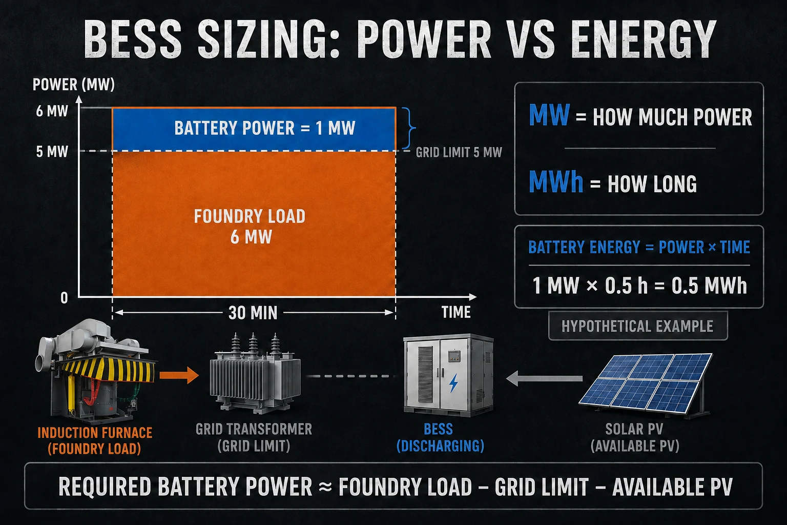
Battery power, measured in kW or MW, determines how much of the foundry’s demand can be supplied at a given moment.
A conceptual screening calculation is:
Required battery power ≈ Foundry load − permitted grid import − available PV power
Consider a hypothetical scenario in which the plant load reaches 6 MW while the desired grid-import limit is 5 MW. If no PV power is available at that moment, the initial power gap is 1 MW.
That does not automatically mean that a 1 MW PCS is the final selection. Engineers must also consider conversion losses, battery auxiliary consumption, control margin, response requirements, environmental conditions, and the PCS overload capability. The load measurement interval must also match the commercial objective: a very short transient and a utility demand measured over a longer averaging window may require different responses.
Battery energy, measured in kWh or MWh, determines how long the power gap can be filled.
A 1 MW shortfall lasting 10 minutes is a different problem from a 1 MW shortfall lasting 90 minutes. The first may be a practical peak-shaving opportunity. The second may indicate that the plant has a sustained power-capacity deficit.
The initial energy requirement is the accumulated load above the chosen grid-import target. Final usable capacity must also account for:
Battery state-of-charge limits
Conversion losses
Required emergency reserve
Temperature and cooling conditions
Battery aging allowance
Charging time before the next peak
Any simultaneous PV-storage objective
The NLR REopt guidance distinguishes electrical load in kW from energy consumption in kWh and evaluates storage size and dispatch using site load, utility rates, costs, and system efficiency. This is the correct general approach: use time-series operating data rather than a simple furnace-capacity ratio.
One-minute data is useful for identifying furnace stages and short load spikes. Data matching the utility’s demand-measurement interval is required for billing analysis. The dataset should cover typical production, high-output periods, shutdowns, and unusual multi-furnace operation.
Where possible, record each furnace and the largest auxiliary loads separately. Mark cold starts, hot starts, holding periods, scrap settling, tapping, furnace changes, and simultaneous heats. Monthly electricity bills may identify an opportunity, but they are rarely detailed enough for final BESS sizing.
A BESS may delay an upgrade when the capacity problem is short, predictable, and followed by enough time to recharge. For example, the transformer may be adequate for the plant’s base load but temporarily constrained when two furnace cycles overlap.
This approach is more credible when:
The excessive load occurs during limited, repeatable periods
A firm maximum grid-import target can be defined
The battery can recharge without creating another demand peak
Production schedules can be coordinated with energy dispatch
Future expansion will not create a continuous capacity deficit
Battery storage is less suitable when several furnaces operate near full power for hours, the battery cannot recover between heats, or planned expansion will permanently exceed the transformer rating.
A feasibility study should model the recovery period as carefully as the discharge period. A battery that reduces the morning peak but creates a new peak while recharging has moved the problem rather than solved it. The plant should compare battery lifecycle cost with transformer expansion, utility upgrades, and production scheduling changes.
A renewable-energy-integrated foundry should not operate its battery on a fixed charge-and-discharge schedule alone. Dispatch should respond to PV output, electricity prices, battery state of charge, the next furnace start, and the plant’s grid-import limit.
For example, midday charging can absorb surplus PV generation. However, if two furnaces are scheduled to overlap later in the shift, sufficient energy must remain available for the expected peak. If outage support is also required, the controller must preserve the specified emergency reserve.
Multi-furnace coordination can reduce the required battery size by adjusting when a cold furnace ramps up, when a noncritical auxiliary load operates, and when the battery recovers. It must not compromise temperature control, casting sequence, cooling water, or safe furnace operation.
The energy plan should therefore be reviewed by both electrical and production teams. A theoretically efficient dispatch schedule can fail in practice if it conflicts with the actual casting schedule.
“Production support” must be translated into a specific list of loads. A foundry should determine whether the battery must support:
The entire furnace at melting power
Reduced-power melting or holding
Control and protection systems
Cooling-water pumps
Dust collection and ventilation
Safe shutdown only
Each option creates a different MW, MWh, transfer-time, and protection requirement. Cooling and safe-shutdown loads should be assessed separately from the full melting load.
A peak-shaving BESS is not automatically an uninterruptible power supply. Full-furnace support requires sufficient PCS power, battery energy, short-circuit and overload capability, switching logic, grounding, protection coordination, and a defined restart sequence. Partial-island or off-grid operation is possible only under properly sized and protected project conditions.
A supplier audit should go beyond the battery-cell certificate. The complete system includes the battery modules, BMS, PCS, EMS, thermal management, fire protection, isolation, grounding, emergency stop, communication, and grid-interconnection protection.
UL explains that UL 9540 addresses energy storage systems and equipment, while UL 9540A is used to evaluate thermal-runaway fire propagation behavior. IEC 62933-5-2:2025 provides lifecycle safety requirements for grid-integrated electrochemical energy storage systems. The applicable standard and edition still depend on the project country, local codes, utility requirements, and authority having jurisdiction.
Compliance at component level should not be presented as proof that the complete installed system meets every local requirement.
A foundry energy management supplier should be able to explain the power flow among the grid, PV generation, storage, conversion equipment, medium-frequency power supply, furnace, and auxiliary loads. It should also define which party is responsible for the battery, PCS, control system, protection, and site integration.
SHENNAI’s ZCIM foundry energy management system is intended to coordinate the grid, photovoltaic generation, storage, AC and DC buses, induction furnace loads, and other plant loads. Depending on the selected topology, the DC bus can reduce some unnecessary repeated AC/DC conversion stages. Actual conversion losses and economic benefits must be calculated for the project configuration.
The control layer can use load data, tariff periods, battery state of charge, and furnace production requirements to coordinate charging and discharging. For a multi-furnace plant, that means managing the total import limit while respecting the operating priority of each furnace.
ZCIM is not itself a furnace. It coordinates downstream equipment such as a full-bridge IGBT medium-frequency power supply and an applicable steel shell induction furnace system.
SHENNAI technical data documents reference full-bridge configurations of 2,000–5,000 kW for certain 3–10-ton systems and 8,000–20,000 kW for certain 10–30-ton systems. These are reference configurations for the documented systems, not universal furnace-selection rules and not BESS sizing values.
The same technical material describes capacitor-coil series resonance, phase-shift phase-lock power regulation, and stable power output as the furnace load changes. In practical terms, series resonance matches the capacitor bank and induction coil as a resonant circuit, while the control system regulates inverter output as the charge condition changes. This gives the energy management layer a defined power-supply interface, but it does not create a fixed battery-saving percentage or guaranteed ROI.
A useful RFQ should include:
Metal type, charge mix, furnace capacity, and target output
Rated and measured furnace input power
Cold-start, hot-start, melting, and holding times
Single-, dual-, or multi-furnace operating sequence
One-minute and utility demand-interval load data
Transformer rating, voltage, current loading, and grid-import limit
Existing power-supply type and single-line diagram
Cooling, dust collection, compressed air, and other major loads
Energy charges, demand charges, and time-of-use periods
Existing or planned PV capacity and hourly generation data
Required peak-shaving target
Critical backup loads, support time, and acceptable transfer time
Planned production expansion
Ambient conditions, installation area, and local safety requirements
These inputs allow SHENNAI to relate the proposed energy architecture to the actual industrial induction melting systems at the site. They also make it possible to separate an economically promising peak-shaving project from a long-duration grid-capacity problem.
Battery energy storage for foundries is most promising when the electrical peak is short, recurring, measurable, and followed by a practical recharge window. It may also increase PV self-consumption and support selected critical loads. It is less likely to replace an electrical upgrade when the capacity deficit lasts for most of the production shift.
A reliable decision starts with real load data, a defined grid-import target, clear production priorities, and an agreed safety boundary. Foundries evaluating ZCIM can request a foundry BESS feasibility review by submitting furnace data, interval load records, transformer information, tariff details, PV output, and the required operating mode.
It can support a defined furnace or critical-load package under properly engineered conditions. Full melting power requires sufficient PCS power, battery energy, transfer capability, protection coordination, cooling, and a controlled restart plan. A system designed only for peak shaving should not be assumed to provide complete furnace backup.
The size cannot be determined from furnace tonnage alone. Required power depends on the difference between actual foundry demand and the permitted grid input. Required energy depends on how long that difference lasts, adjusted for SOC limits, losses, reserve capacity, charging time, and battery aging.
It may delay an upgrade when excess demand is short and predictable. It is unlikely to be the right substitute when the plant exceeds transformer capacity for long periods or planned expansion creates a permanent load increase. Both options should be compared using lifecycle cost and production constraints.
Yes, under an appropriately designed control and power architecture. Reliable coordination requires furnace-level load data, production priorities, a maximum grid-import target, and enough charging time between peaks. Continuous simultaneous operation can substantially increase both the battery power and energy requirement.

In the forging workshop, industrial furnaces smelt metals, including cupola, induction furnace, resistance furnace, electric arc furnace, vacuum furnace, open hearth furnace, crucible furnace, etc; There are sand mold drying furnace for baking sand mold, ferroalloy drying furnace and casting annealing furnace, etc; In the forging workshop, there are various heating furnaces for heating ingots or billets before forging and heat treatment furnaces for relieving stress after forging;
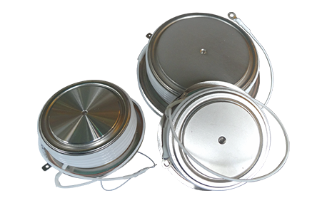
The most effective way for the failure of the medium frequency furnace is to use the low current experiment to judge whether it is the fault of the rectifier circuit or the fault of the inverter part. In the low current experiment, when the DC voltage is less than 513v, it indicates that there is a phase loss fault in the DC rectifier part. Check the specific thyristor fault, and the pulse breaking method should be used to judge whether it is the thyristor fault or there is no trigger pulse.
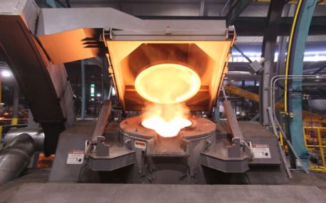
The most effective method for the failure of the intermediate frequency furnace is to use a small current experiment to judge whether the rectifier circuit is faulty or part of the inverter fault. When the DC current is less than 513 volts

Please send us your request and we will reply to you within 24 hours.
We will get in touch with you as soon as possible
