- Tel:+8616638907067
- Email:[email protected]
A renewable-energy-ready foundry is not simply a plant with solar panels or a battery beside the transformer. It is a melting operation designed so that furnace duty, electrical infrastructure, cooling, controls, and future energy assets can work together without limiting production. For a new plant or expansion project, renewable energy foundry planning should begin with excerpt …
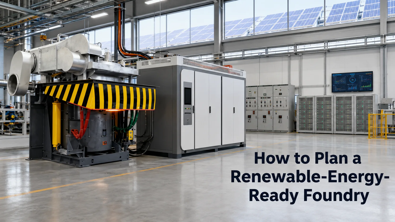
A renewable-energy-ready foundry is not simply a plant with solar panels or a battery beside the transformer. It is a melting operation designed so that furnace duty, electrical infrastructure, cooling, controls, and future energy assets can work together without limiting production.
For a new plant or expansion project, renewable energy foundry planning should begin with the melting schedule and load profile, not with photovoltaic capacity. A correctly sequenced plan helps a foundry avoid an undersized transformer, incompatible power architecture, poor battery economics, or a solar installation that cannot meaningfully support its highest-value operating periods.
“Renewable-energy-ready” does not mean guaranteed zero-carbon operation. It means the factory is engineered to collect the right data, accommodate future photovoltaic and storage systems, and coordinate electricity use when site conditions, tariffs, production requirements, and protection design make those investments practical.
The first decision is operational: what should renewable readiness accomplish for this specific foundry?
For one plant, the priority may be reducing demand charges during simultaneous melting. For another, it may be using daytime solar generation to support a predictable melting shift. A third plant may need better resilience where the grid is weak or where transformer expansion is delayed. These are different objectives and should not be forced into one equipment specification.
A practical definition normally includes:
Furnace and power-supply capacity matched to the required production rate.
A transformer, switchgear, cable system, and protection scheme sized for the actual load profile.
Cooling capacity for the selected furnace, power supply, and planned duty cycle.
Metering that separates furnace energy, auxiliary loads, and generation or storage flows.
Space, cable routes, control interfaces, and electrical provisions for future PV or battery storage.
A control strategy for prioritizing production, safe operation, and energy cost management.
A plant may still operate mainly on grid electricity after this preparation. The value is that later renewable-energy additions do not require a major redesign of the furnace room, transformer bay, or control architecture.
A furnace’s tonnage rating does not describe how much metal a plant will ship per shift. Production planning must account for charge condition, metal type, cold-start and hot-start practice, melting time, holding time, tapping sequence, refractory practice, and planned downtime.
Start an RFQ with these questions:
Which metals and charge materials will be melted?
What is the required output per hour, shift, and year?
Will the furnace operate primarily in melting mode, holding mode, or both?
How often will the plant start from a cold furnace?
Will one furnace melt while another holds metal or receives a new lining?
Is future capacity expansion expected within the next few years?
These answers determine whether a single furnace, dual-furnace arrangement, or multiple independently scheduled furnaces is appropriate. They also define the electrical peak that the plant, rather than the individual furnace, must manage.
For a project focused on robust, continuous melting, a steel shell induction furnace configuration may be part of the production plan. The furnace body, coil, cooling arrangement, and power supply must be treated as a matched system. Choosing the shell type first and treating the power system as a later procurement item can create an avoidable bottleneck.
A renewable-energy project should be based on time-series demand, not an annual electricity bill alone. Induction melting loads can change quickly between cold charge, melting, superheating, holding, and periods when multiple furnaces operate at once.
Record or estimate, at minimum:
| Planning input | Why it matters |
|---|---|
| Maximum simultaneous melting power | Sizes transformer, switchgear, cables, and demand-management strategy |
| Average power by shift | Helps evaluate PV self-consumption and storage duty |
| Melting and holding schedule | Shows when energy can be shifted without disrupting output |
| Auxiliary loads | Includes cooling, dust collection, pumps, cranes, compressors, and controls |
| Existing peak-demand charges | Indicates whether storage or load coordination deserves deeper analysis |
| Planned expansion loads | Prevents an energy system from being stranded by the next furnace purchase |
The key metric is not “How much solar can fit on the roof?” It is “When does the plant need power, how much does it need, and which loads can be coordinated without reducing melt-shop output?”
An induction furnace power supply, cooling plant, dust extraction system, material handling equipment, and other plant loads may overlap. The transformer and distribution design therefore need a diversity assessment based on realistic operating modes, not a simple addition of nameplate ratings and not an assumption that every load is independent.
The engineering team should examine:
Incoming supply voltage and available utility capacity.
Transformer rating, impedance, and expansion margin.
Main switchgear fault rating and protection coordination.
Harmonic, reactive-power, and power-quality requirements imposed by the local utility.
Cable lengths, conductor sizing, earthing, and equipment-room ventilation.
Which loads are essential during a grid event and which can be shed.
A battery cannot correct an undersized transformer or inadequate protection system. It may reduce selected peaks when designed for the required duration and control response, but it should be evaluated after the base electrical design is sound.
The induction power supply affects melting productivity, controllability, maintenance planning, and the type of energy data that can be collected. For this reason, the power-supply decision should be made alongside the furnace and electrical design.
A full-bridge IGBT solution may be considered where the operating model benefits from modern control, load matching, and future monitoring integration. SHENNAI’s full-bridge IGBT architecture uses a capacitor-coil series-resonant circuit and phase-shift/phase-locked regulation. In practical terms, the buyer should ask how the system maintains usable power through normal changes in charge condition and furnace operation, rather than relying only on a cabinet nameplate.
The correct question is not whether one technology is universally better. It is whether the proposed power system is appropriate for the metal, furnace capacity, duty cycle, service resources, transformer limits, and expansion plan. Use the full-bridge IGBT power-supply selection guide and the IGBT power-supply sizing checklist to compare these inputs before finalizing the electrical scope.
Solar generation can contribute valuable daytime energy, but its output changes with weather, season, roof orientation, shading, and local conditions. A foundry’s furnace load is also variable, but it is usually driven by production commitments rather than sunlight.
PV is most useful when the plant can consume generation directly during operating hours or when a designed storage and control strategy can shift part of that energy. It is less compelling when the furnace’s critical melting period consistently occurs outside the solar window and no viable storage, export, or load-shifting path exists.
The feasibility study should compare:
Expected solar production by hour and season.
Furnace and auxiliary demand by hour.
Local import, export, and demand-charge rules.
Roof or ground area, structural limits, and shading.
Planned battery capacity, warranty conditions, and cycle duty.
Production restrictions that prevent load shifting.
For a more focused feasibility discussion, link readers to solar power and battery storage for an induction furnace. That article should answer whether solar and storage can support a particular melting duty; this planning guide addresses how the whole foundry should be prepared before that decision.
Battery energy storage is not automatically justified because a plant has high electricity consumption. It needs a defined job.
Possible jobs include peak shaving during planned overlap, absorbing PV generation that would otherwise be curtailed, supporting a controlled ramp-up, or reducing selected grid imports under suitable tariffs. The right battery size depends on required kW, required kWh, discharge duration, permissible depth of discharge, control logic, ambient conditions, and safety and protection requirements.
Do not size a battery from furnace capacity alone. A high-power, short-duration peak and a lower-power, multi-hour production interval need very different storage designs.
A possible DC-bus architecture can also be evaluated when PV, storage, and power-electronic furnace loads are part of one integrated system. Depending on configuration, this may reduce unnecessary AC/DC conversion stages. It is not a universal efficiency guarantee: compatibility, protection, maintenance access, local code requirements, and controls must be reviewed by qualified engineers.
A plant cannot manage what it does not measure. Even when PV and storage are planned for a later phase, install the metering, communication routes, and data structure in the initial project.
At minimum, collect data for furnace power, energy per melt or per ton where practical, holding time, cooling-system energy, auxiliary loads, transformer loading, maximum demand, and production state. These records help management distinguish a true energy opportunity from a production or maintenance problem.
For multi-furnace operations, the controls should also show when loads overlap and whether those overlaps are necessary. A dual-furnace arrangement may support continuous production, but uncontrolled simultaneous melting can create avoidable peaks. The operational target is not simply lower power. It is the best combination of metal availability, melting time, quality control, and site electricity cost.
SHENNAI’s ZCIM concept is relevant at this plant-management layer. Its published system architecture shows coordination among grid supply, photovoltaic generation, battery storage, AC and DC buses, and induction-furnace loads. This should be specified as an energy-management and coordination layer, not as a replacement for the furnace or power supply itself.
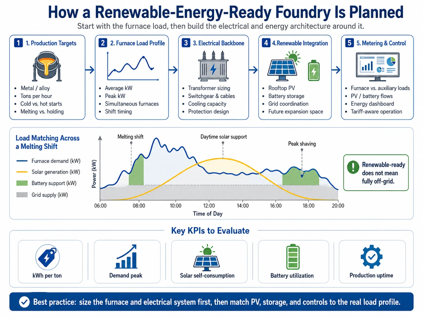
A staged plan is often more defensible than attempting to install every future energy asset on day one.
Phase 1: Build the production foundation.
Confirm furnace layout, transformer and switchgear capacity, cooling, power supply, protection, and metering. Reserve physical and electrical space for future expansion.
Phase 2: Establish a baseline.
Operate long enough to collect credible production and power data across normal shifts, metal grades, and seasonal conditions. Verify where peak demand occurs and whether it is operationally avoidable.
Phase 3: Add the best-supported energy asset.
This may be PV, storage, demand management, or additional controls. The choice should follow measured load behavior and local commercial conditions.
Phase 4: Integrate and refine.
Coordinate generation, storage, furnace schedules, and auxiliary loads through a defined control hierarchy. Production continuity and equipment protection must take priority over an energy-saving target.
This approach does not delay decarbonization. It reduces the risk of spending capital on an energy asset that does not fit the foundry’s actual operating pattern.
A useful RFQ should allow suppliers to size the furnace and future energy interfaces from the same operating data. Include:
Metal types, charge mix, furnace capacity, and target melt rate.
Required output per shift and annual production plan.
Cold-start, hot-start, holding, and tapping practices.
Single-furnace, dual-furnace, or multi-furnace operating scenarios.
Site voltage, transformer capacity, available utility capacity, and protection information.
Existing or planned PV capacity, site area, and expected installation phase.
Battery objectives: peak shaving, solar self-consumption, resilience, or another defined duty.
Cooling-water source, ambient conditions, dust-control requirements, and layout limits.
Energy tariff structure, peak-demand charges, and operating schedule.
Required data points, communication protocols, and plant monitoring expectations.
Expansion plan for future furnace capacity or additional production lines.
A supplier should be able to explain the boundaries of its scope: furnace body, power supply, cooling, transformer interface, metering, control integration, PV and storage interface, commissioning, and service support. Vague “energy-saving system” wording is not enough for a capital project.
Luoyang Shennai Power Equipment Co., Ltd. can be evaluated as an integrated equipment partner where the project requires alignment among furnace body, induction power supply, monitoring, and later energy-management integration.
For the initial melting system, the buyer should first confirm capacity, metal, operating duty, electrical conditions, cooling requirements, and service expectations. SHENNAI can then match a steel-shell furnace and full-bridge IGBT power-supply scope to those project inputs. For later energy phases, the ZCIM system concept provides a basis for discussing grid, PV, storage, and multiple furnace-load coordination.
The procurement decision should still be evidence-based. Request a single-line diagram, load assumptions, scope boundaries, control points, protection responsibilities, and the data needed for future integration. That documentation matters more than a broad claim that a foundry is “green” or “zero carbon.”
A renewable-energy-ready foundry is built by sequencing decisions correctly: production target first, furnace and power system second, electrical backbone and cooling third, then metering, PV, storage, and supervisory control. This order protects melting capacity while keeping future energy options open.
For a project review, contact SHENNAI’s engineering team with the metal type, furnace capacity, required output, existing transformer data, operating schedule, cooling conditions, current energy-cost issues, and any planned PV or battery scope. Those inputs make it possible to discuss an implementable furnace and energy roadmap rather than a generic renewable-energy package.
It may be possible in specific projects, but it is not a default outcome. It depends on furnace load, production schedule, solar resource, PV size, storage capacity, grid availability, protection design, and the acceptable level of production risk. A renewable-energy-ready design prepares the plant for evaluation; it does not guarantee off-grid operation.
Not necessarily. The decision should be based on the job the battery must perform, such as peak shaving, solar self-consumption, or controlled backup. A measured load profile and local tariff analysis should come before either investment.
There is no universal multiplier. The transformer must be sized from simultaneous furnace operation, power-supply input requirements, auxiliary loads, planned expansion, power quality, and applicable utility requirements. Use actual operating scenarios rather than furnace nameplate capacity alone.
Collect time-stamped furnace power, total plant demand, auxiliary-load consumption, transformer loading, operating states, production quantity, holding time, and utility tariff information. This allows the project team to identify when energy is used and which peaks are operationally necessary.
No. A DC-bus design may reduce conversion stages in certain integrated architectures, but the outcome depends on the selected equipment, operating mode, control strategy, protection design, and site conditions. It should be assessed as part of a complete engineering proposal.
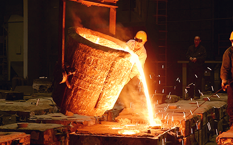
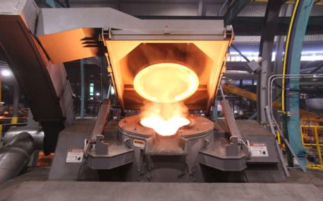
In the forging workshop, industrial furnaces smelt metals, including cupola, induction furnace, resistance furnace, electric arc furnace, vacuum furnace, open hearth furnace, crucible furnace, etc; There are sand mold drying furnace for baking sand mold, ferroalloy drying furnace and casting annealing furnace, etc; In the forging workshop, there are various heating furnaces for heating ingots or billets before forging and heat treatment furnaces for relieving stress after forging;
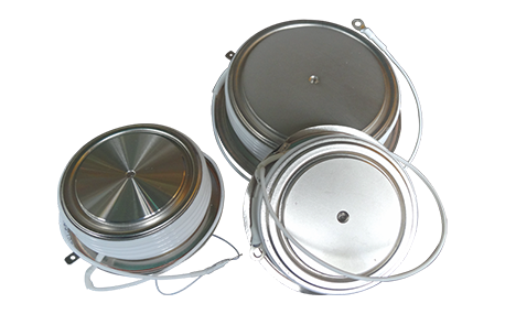
The most effective way for the failure of the medium frequency furnace is to use the low current experiment to judge whether it is the fault of the rectifier circuit or the fault of the inverter part. In the low current experiment, when the DC voltage is less than 513v, it indicates that there is a phase loss fault in the DC rectifier part. Check the specific thyristor fault, and the pulse breaking method should be used to judge whether it is the thyristor fault or there is no trigger pulse.
The most effective method for the failure of the intermediate frequency furnace is to use a small current experiment to judge whether the rectifier circuit is faulty or part of the inverter fault. When the DC current is less than 513 volts

Please send us your request and we will reply to you within 24 hours.
We will get in touch with you as soon as possible
