- Tel:+8616638907067
- Email:[email protected]
For a multi-furnace foundry, the inverter decision should start with the operating schedule, not a generic claim that series or parallel is better. A series-resonant system can offer flexible allocation, while a parallel-resonant system may remain practical when existing transformers, capacitors, coils, and maintenance skills favor it. The choice depends on simultaneous demand, transformer loading, excerpt …
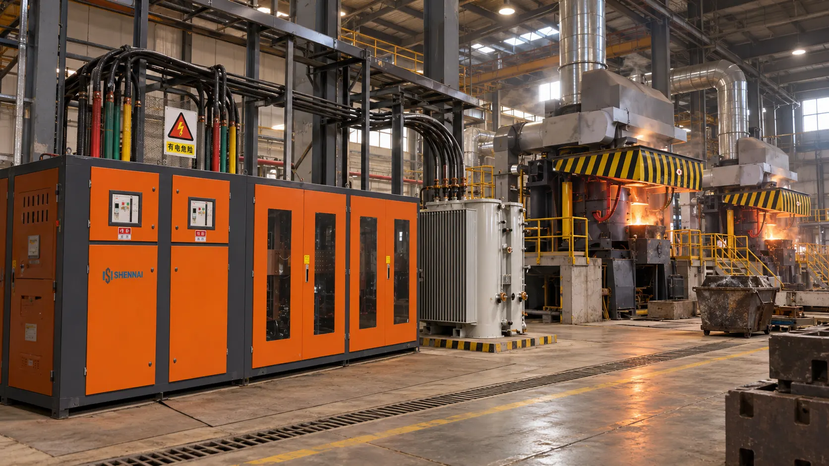
For a multi-furnace foundry, the inverter decision should start with the operating schedule, not a generic claim that series or parallel is better. A series-resonant system can offer flexible allocation, while a parallel-resonant system may remain practical when existing transformers, capacitors, coils, and maintenance skills favor it. The choice depends on simultaneous demand, transformer loading, fault isolation, grid limits, and retrofit cost.
This guide focuses on plant-level decisions and complements the series and parallel inverter comparison. SCR and IGBT describe switching devices; series and parallel describe resonant-circuit architecture. A quotation should identify both the device family and the complete topology.
A one-to-two or one-to-multiple arrangement can mean very different things. One system may switch full power between furnaces; another may melt in one while holding in a second. A third may regulate both simultaneously. Before comparing hardware, write an operating matrix for every production state.
Record which furnace melts, holds, superheats, sinters a lining, or waits in each state. Add expected kilowatts and duration, and state whether simultaneous operation is mandatory. This prevents a quotation from treating two installed furnaces as simultaneous full-power loads when the schedule does not require it—or assuming diversity when production needs both available.
The matrix should also show alloy changes, tap sequence, molding-line demand, planned maintenance, and response to a furnace or cabinet fault. It becomes the basis for power-sharing controls, transformer capacity, cooling, switchgear, and production-risk evaluation.
In a series-resonant circuit, the capacitor and induction load form a series path. The power supply is commonly treated as a voltage-source architecture, although the exact front end and control method vary. Modern implementations can regulate output through frequency, phase shift, or other supplier-specific methods. This can support high power factor and stable power across useful operating conditions when the transformer, rectifier, resonant circuit, and controls are coordinated.
For multiple furnaces, the advantage is not the word series itself. It is whether the system provides independent inverter channels or a documented power-allocation method. The SHENNAI medium-frequency power supply range includes configurations for multi-output melting and adjustable distribution; operating modes and the total power ceiling must be confirmed for the selected model.
A traditional parallel inverter normally uses a current-source DC link feeding a parallel resonant load. Its behavior, commutation margin, power factor, and response to load changes depend on the detailed circuit and control design. These systems can remain serviceable for established high-power installations, particularly where the plant already owns compatible transformers, reactors, capacitor banks, coils, spares, and test procedures.
The retrofit limitation is often system integration rather than melting capability. Adding independent outputs may require new switching, isolation, controls, protection, and cooling. A low cabinet price does not mean lower installed cost if the electrical room must change.
Power sharing should be specified as a set of operating rules. If the connected inverter capacity is 2,000 kW, can two furnaces each receive 1,000 kW, or can one receive 1,600 kW while the other holds at 400 kW? Can the operator change that split continuously? What happens when one load detunes, arcs, or reaches a current limit? Marketing terms such as dual output do not answer these questions.
Ask for a mode diagram and logged performance under representative loads. Confirm total simultaneous output, minimum stable holding power, transfer behavior, independent protection, restart sequence, and whether a fault on one channel stops the other. Verify useful power during charge collapse and superheating, not only nameplate power on a favorable test load.
For a foundry supplying continuous casting or automated molding, controlled overlap between melting and holding can reduce waiting and improve metal availability. Calculate the value from the production schedule, not equipment count.
A shared transformer can be used effectively when controls prevent unmanaged peaks and direct power to the furnace that needs it. That does not reduce capacity automatically. The transformer must cover permitted load, converter losses, auxiliaries, harmonic duty, temperature rise, site derating, and reserve.
Start with each operating state and convert real input power to apparent power using the applicable power factor. Check transformer secondary voltage, winding arrangement, impedance, taps, rectifier pulse count, and short-circuit capacity. A 12-pulse or higher-pulse front end may require phase-shifted secondary windings. Pulse count influences harmonics but does not alone determine usable output or transformer size.
SHENNAI describes multi-output operation, high transformer utilization, and flexible distribution for applicable configurations. Treat these as model-dependent features. Request a single-line diagram and load table identifying transformer, rectifier sections, inverter channels, furnace disconnects, capacitors, and cooling circuits.
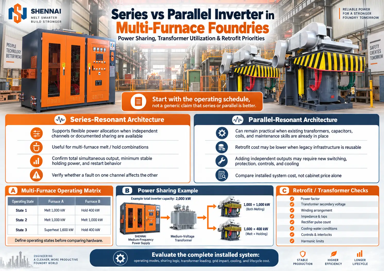
A retrofit should preserve equipment only when it remains electrically and thermally compatible. A series solution may deserve closer evaluation when the project needs independent outputs, broader power allocation, improved part-load operation, or a new multi-pulse front end. Keeping or extending a parallel system may be rational when its measured output, reliability, grid performance, and maintenance cost are acceptable and the existing infrastructure has substantial remaining life.
Do not plan a cabinet-only replacement until the supplier has checked:
Transformer primary and secondary voltage, kVA, impedance, taps, and winding connections
Rectifier pulse arrangement and plant harmonic limits
Furnace capacity, coil inductance, rated current, and operating frequency
Capacitor-bank rating and series or parallel connection
Busbars, water-cooled cables, disconnects, grounding, and protection
Cooling-water flow, pressure, inlet temperature, quality, and heat rejection
PLC interfaces, furnace switching, interlocks, alarms, and data logging
Available floor space, cable routes, shutdown window, and commissioning plan
If the topology changes the resonant circuit, the existing coil or capacitor bank may not be reusable. Higher output can expose cooling or transformer limits hidden by the old system. A staged retrofit can reduce shutdown risk when temporary interfaces and protection are engineered in advance.
Require every bidder to price the same production case and electrical boundary. Compare continuous usable power, not only maximum cabinet kilowatts. Request power factor and harmonic data at defined load points and measurement locations. Include transformer changes, switchgear, capacitors, cooling, installation, commissioning, spares, training, and the cost of planned downtime.
A useful acceptance test should use agreed metal, charge condition, batch weight, tapping temperature, and production sequence. Use the same boundary applied when evaluating induction furnace electricity use per ton. Record melt and holding time, active power, current and voltage limits, kilowatt-hours per net tapped ton, power factor, trips, and restart time. These measurements show whether the topology and sharing logic improve the process.
Use the SCR and IGBT selection guide when the semiconductor choice is open. For a preliminary review, SHENNAI needs furnace count and capacity, metal and hourly output target, simultaneous modes, incoming voltage, transformer data, topology, coil and capacitor information, cooling conditions, and retrofit scope.
Series versus parallel inverter selection in a multi-furnace foundry is a system decision. Series-resonant configurations can support flexible power allocation when they include suitable independent channels and controls. Parallel-resonant systems can remain economical where existing infrastructure and operating practice fit the production duty. In either case, transformer utilization improves only when the load schedule, total power limit, grid interface, cooling, and protection are coordinated.
Build the operating matrix first, require comparable single-line diagrams and load data, and evaluate the complete installed and lifecycle cost. Project teams can request an application-specific fit check before fixing the transformer, inverter, or retrofit scope.
Yes, when the transformer, rectifier, inverter channels, protection, controls, and cooling system are designed for the permitted simultaneous demand. The operating modes and total power ceiling must be defined.
No. Energy per tapped ton depends on usable power, load matching, charge practice, holding time, furnace condition, cooling, and the complete converter design. Compare measured heats under equivalent conditions.
Possibly, but it is rarely a simple cabinet swap. The transformer, reactor, capacitor bank, coil, cables, protection, controls, and cooling must be checked for the new resonant architecture.
Not necessarily. Some systems share a fixed total power limit; others use separately rated channels. The supplier should state the simultaneous output, allowable power split, and fault behavior.
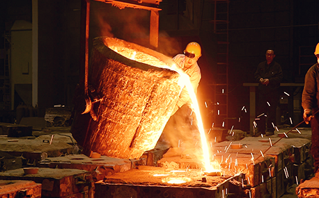
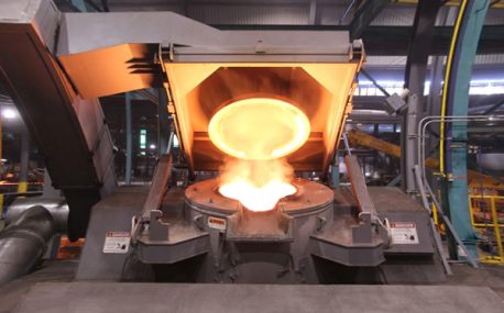
In the forging workshop, industrial furnaces smelt metals, including cupola, induction furnace, resistance furnace, electric arc furnace, vacuum furnace, open hearth furnace, crucible furnace, etc; There are sand mold drying furnace for baking sand mold, ferroalloy drying furnace and casting annealing furnace, etc; In the forging workshop, there are various heating furnaces for heating ingots or billets before forging and heat treatment furnaces for relieving stress after forging;
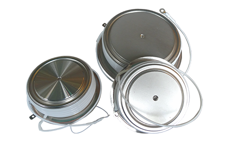
The most effective way for the failure of the medium frequency furnace is to use the low current experiment to judge whether it is the fault of the rectifier circuit or the fault of the inverter part. In the low current experiment, when the DC voltage is less than 513v, it indicates that there is a phase loss fault in the DC rectifier part. Check the specific thyristor fault, and the pulse breaking method should be used to judge whether it is the thyristor fault or there is no trigger pulse.
The most effective method for the failure of the intermediate frequency furnace is to use a small current experiment to judge whether the rectifier circuit is faulty or part of the inverter fault. When the DC current is less than 513 volts

Please send us your request and we will reply to you within 24 hours.
We will get in touch with you as soon as possible
