- Tel:+8616638907067
- Email:[email protected]
A 1-to-4 induction furnace system can increase usable production from the same electrical room when its total power is actively shared across four furnace outputs. The objective is not to make four furnaces draw full nameplate power at once. It is to coordinate melting, holding, charging, and pouring so the available transformer capacity follows the excerpt …
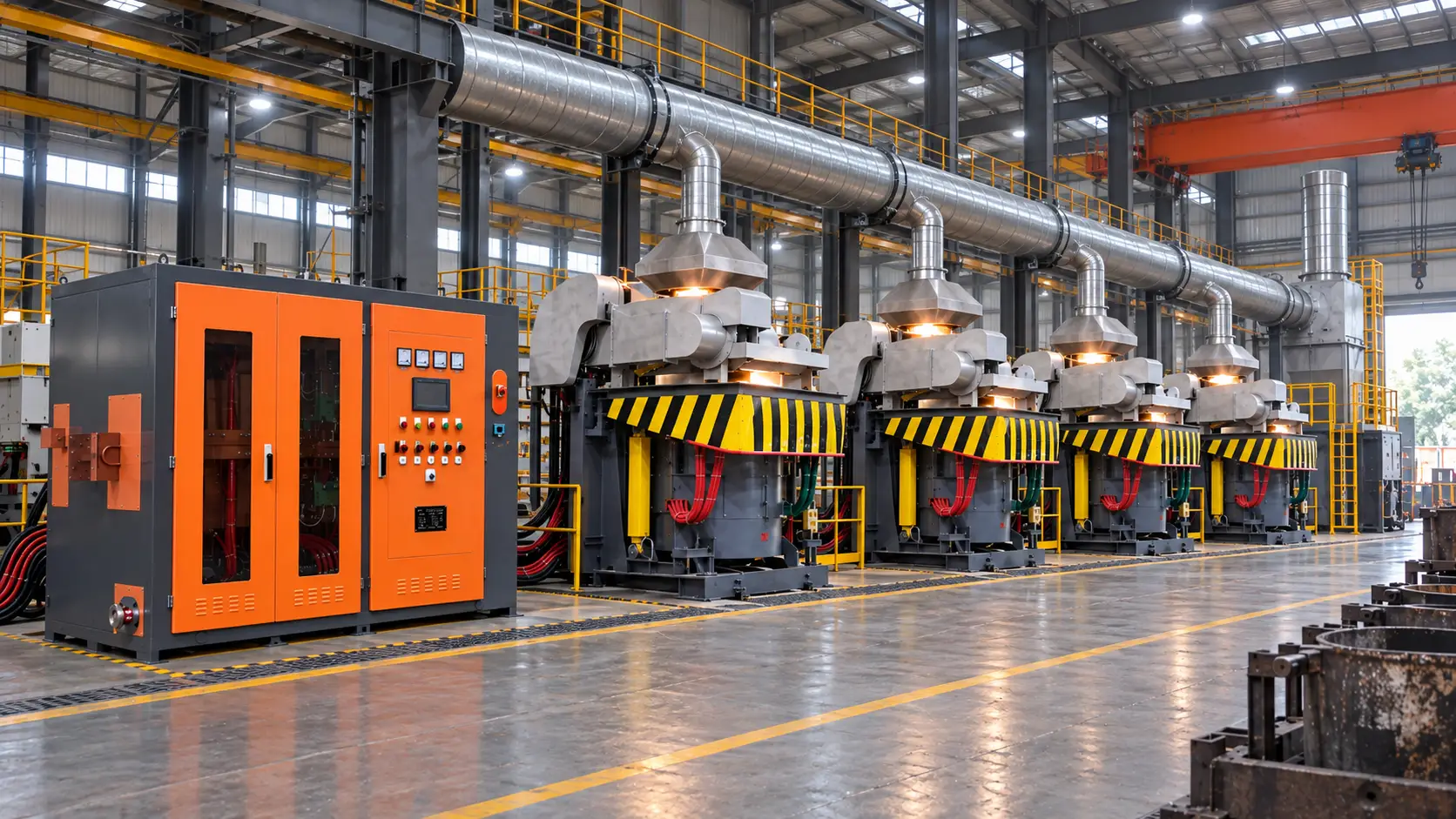
A 1-to-4 induction furnace system can increase usable production from the same electrical room when its total power is actively shared across four furnace outputs. The objective is not to make four furnaces draw full nameplate power at once. It is to coordinate melting, holding, charging, and pouring so the available transformer capacity follows the production schedule. A successful design therefore combines a multi-output power cabinet, furnace switching, resonant components, protection, cooling, and operating rules.
This approach is different from simply adding a fifth transformer or oversizing the existing one. It can be attractive when the transformer has spare thermal and electrical margin but the plant loses time while furnaces wait for power. The actual gain depends on simultaneous load, power factor, furnace condition, casting rhythm, and the limits of the selected configuration.
The phrase 1-to-4 describes one power-supply system serving up to four furnace circuits. It does not, by itself, promise four simultaneous full-power melts. Some plants use one furnace at high power, a second at holding power, and keep two circuits ready for rapid transfer. Others run two furnaces together and rotate the remaining outputs through the batch cycle. Define these states before selecting equipment.
Build a 24-hour operating matrix with furnace ID, alloy, batch weight, target tap temperature, melt kilowatts, holding kilowatts, and duration. Mark charging, slag removal, tapping, lining sinter, maintenance, and standby periods. The matrix exposes the diversity that can be used without compromising production and identifies the short intervals when a power-sharing limit could become a bottleneck.
For a continuous casting or automated molding line, include the required metal buffer and tapping sequence. A system that looks adequate on average may still fail if all four furnaces demand peak power in the same five-minute window.
Output rises when idle time falls. If one furnace is waiting for a dedicated converter while another is below its useful power level, a shared system can redirect capacity to the active furnace. Independent output channels or a controlled switching matrix can support melt-and-hold combinations, sequential high-power melting, and rapid transfer after a tap.
Specify the control envelope instead of relying on the label “multi-output.” Ask for the maximum simultaneous real power, minimum stable holding power, allowable split between channels, transfer time, and behavior when a coil detunes or a furnace trips. Confirm whether a fault on one output isolates that circuit or interrupts the complete supply. These details determine whether the system improves throughput or only changes the wiring.
The medium-frequency power supply offered by SHENNAI is described for multi-output melting and flexible power distribution in applicable configurations. Treat the number of outputs, power ceiling, and operating modes as model-dependent and verify them against the proposed single-line diagram.
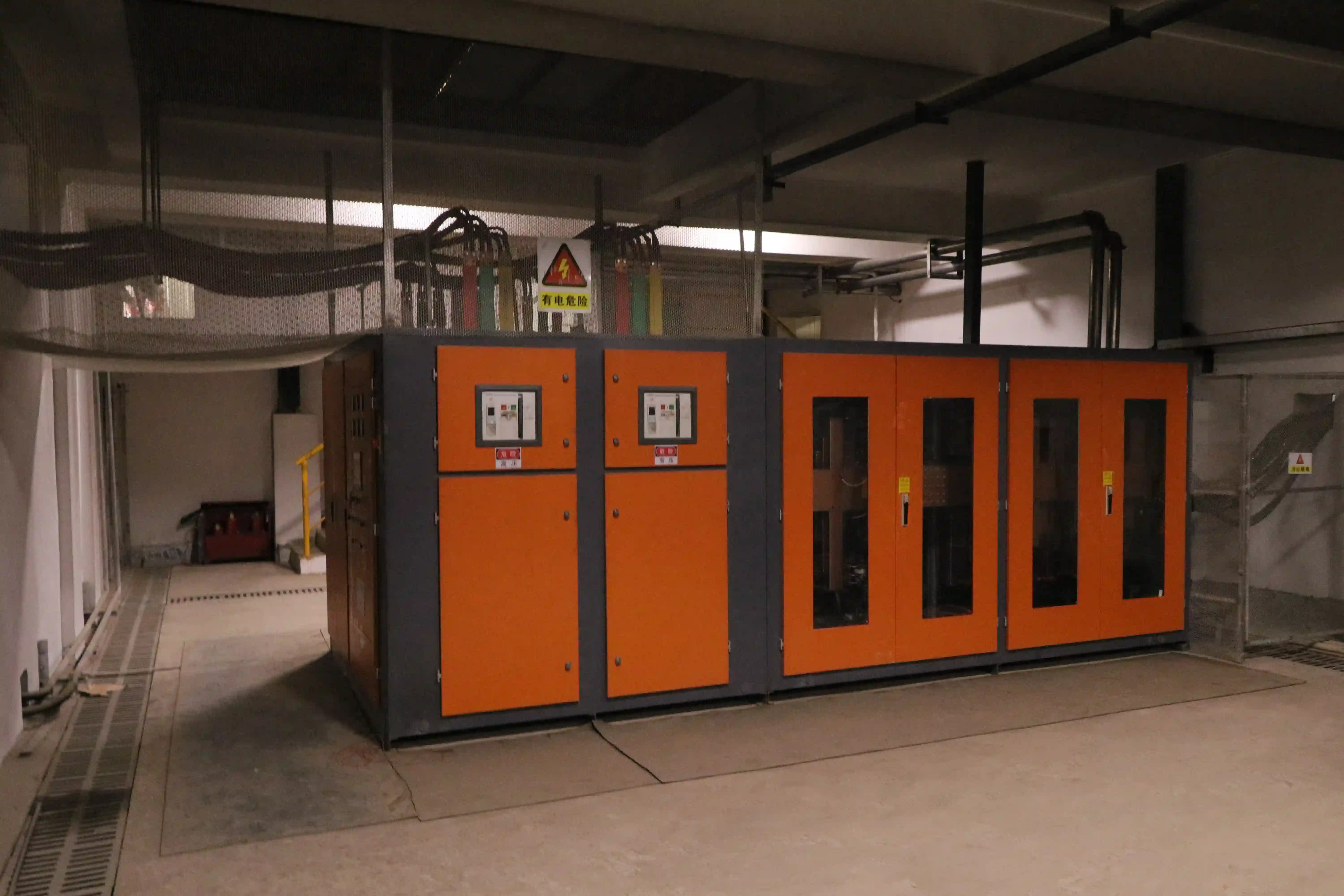
A shared transformer still has a finite kVA, temperature-rise, short-circuit, and harmonic-duty limit. Power sharing improves utilization by reducing uncontrolled peaks and keeping more of the transformer’s available capacity productive. It does not justify exceeding the nameplate or removing engineering reserve.
For every operating state, convert expected real input power to apparent power with the applicable power factor. Then check primary and secondary voltage, impedance, taps, winding arrangement, rectifier pulse count, cable ampacity, and cooling. If the design uses a 12-pulse or higher-pulse front end, confirm the phase-shifted transformer secondaries and harmonic study. Pulse count can help grid performance, but it does not determine usable furnace output by itself.
Compare the diversified maximum—not the sum of four furnace nameplates—with the transformer’s continuous rating. Include converter losses, auxiliary loads, ambient temperature, site derating, and a reserve for charge collapse or superheating. The result is a defensible capacity calculation rather than an assumption that four outlets require four times the transformer.
A series-resonant arrangement is often evaluated when the project needs flexible output allocation, high power factor, and multiple furnace circuits. The practical advantage comes from the complete topology: rectifier, DC link, inverter channels, resonant capacitors, furnace disconnects, controls, and protection. A series circuit may still require limits on total simultaneous power and must be matched to each coil and operating frequency.
A parallel-resonant installation can remain sensible when an existing plant already has compatible transformers, reactors, capacitor banks, coils, spares, and technicians. Converting it to four independently managed outputs may require more than a cabinet replacement. Check commutation behavior, isolation, switching sequence, cooling, and interlocks before assuming the old resonant components can be reused.
For a semiconductor-level decision, the SCR and IGBT selection guide explains why device family and resonant architecture should be specified separately. The 1-to-4 decision is primarily a plant integration question: which topology can deliver the required operating matrix with acceptable retrofit risk?
Request a site survey or drawing review before freezing the quotation. The supplier should verify:
A topology change can make an existing coil or capacitor bank electrically unsuitable even when the furnace shell is reusable. Higher productive output can also reveal weaknesses in cooling, busbars, or transformer ventilation. Plan a staged cutover only when temporary protection and safe bypass arrangements are documented.
Use an acceptance test based on the same metal, batch weight, charge condition, tapping temperature, and production sequence before and after the retrofit. Record melt time, holding time, active input power, power factor, kWh per net tapped ton, furnace waiting time, transfers, trips, and restart time. The relevant comparison is the completed production schedule, not the largest number printed on a nameplate.
Use the same electrical boundary applied when reviewing induction furnace electricity use per ton. Include transformer losses and auxiliaries consistently. A 1-to-4 system may increase tons per shift by reducing waiting even when its peak input power is unchanged; conversely, poor switching logic can create bottlenecks that erase the expected benefit.
For an application review, provide furnace count and capacity, metal and hourly output target, simultaneous operating modes, incoming voltage, transformer data, existing topology, coil and capacitor information, cooling conditions, layout drawings, and the desired retrofit scope. This lets SHENNAI test the power-sharing concept against the real duty cycle.
A 1-to-4 multi-power induction furnace system can raise output without adding transformer capacity when it converts idle electrical margin into controlled production time. The decision rests on an operating matrix, diversified kVA calculation, independent output behavior, resonant compatibility, cooling and protection, and a measured acceptance test. Multi-output capability is valuable only when its limits are explicit and matched to the foundry schedule.
Start with the four-furnace duty cycle, then compare complete installed and lifecycle cost. Teams can request a multi-furnace application fit check with their transformer, furnace, coil, cooling, and production data before selecting the final configuration.
Yes, if the transformer, rectifier, inverter channels, switching, protection, and cooling are designed for the permitted simultaneous demand. The total power ceiling must be defined.
Not necessarily. It may mean one shared power system with four selectable outputs and a controlled total limit. Confirm the allowable power split and simultaneous output.
Possibly, but coil inductance, rated current, frequency, capacitor values, cables, and protection must be checked against the new resonant circuit.
No. Throughput improves only when power allocation, switching logic, charging, tapping, and operator procedures match the production schedule.
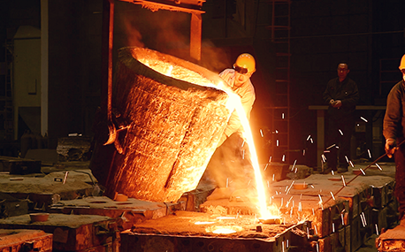
In the forging workshop, industrial furnaces smelt metals, including cupola, induction furnace, resistance furnace, electric arc furnace, vacuum furnace, open hearth furnace, crucible furnace, etc; There are sand mold drying furnace for baking sand mold, ferroalloy drying furnace and casting annealing furnace, etc; In the forging workshop, there are various heating furnaces for heating ingots or billets before forging and heat treatment furnaces for relieving stress after forging;
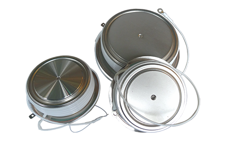
The most effective way for the failure of the medium frequency furnace is to use the low current experiment to judge whether it is the fault of the rectifier circuit or the fault of the inverter part. In the low current experiment, when the DC voltage is less than 513v, it indicates that there is a phase loss fault in the DC rectifier part. Check the specific thyristor fault, and the pulse breaking method should be used to judge whether it is the thyristor fault or there is no trigger pulse.
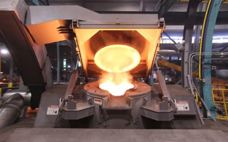
The most effective method for the failure of the intermediate frequency furnace is to use a small current experiment to judge whether the rectifier circuit is faulty or part of the inverter fault. When the DC current is less than 513 volts

Please send us your request and we will reply to you within 24 hours.
We will get in touch with you as soon as possible
