- Tel:+8616638907067
- Email:[email protected]
Selecting an induction furnace shell for a retrofit is an integration decision, not a simple steel-versus-aluminum price comparison. The shell must fit the existing transformer, medium-frequency power supply, coil, capacitor bank, cooling circuit, tilting method, foundation, and production schedule. A structurally strong furnace can still perform poorly if the transformer or cooling loop is undersized. excerpt …
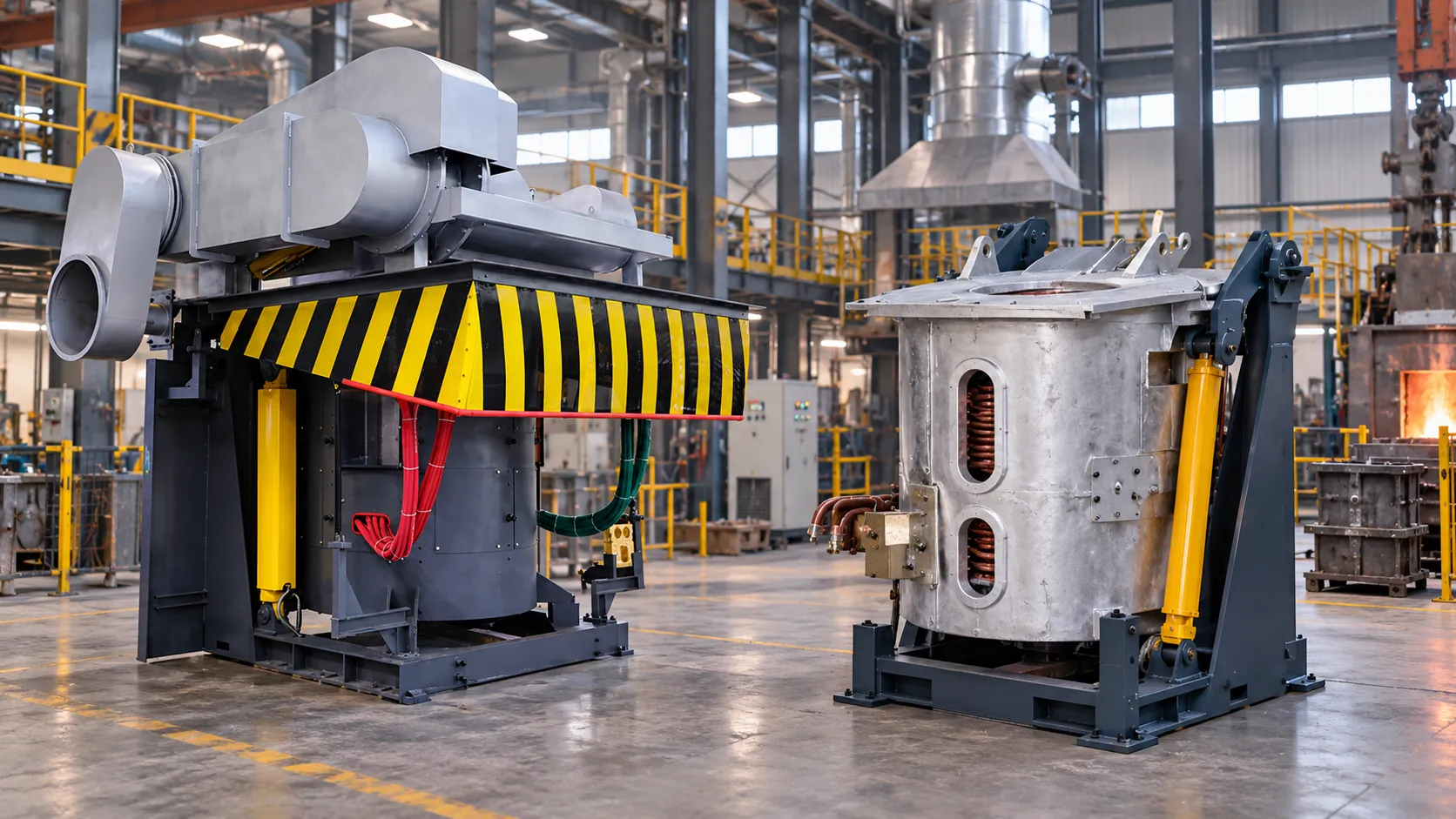
Selecting an induction furnace shell for a retrofit is an integration decision, not a simple steel-versus-aluminum price comparison. The shell must fit the existing transformer, medium-frequency power supply, coil, capacitor bank, cooling circuit, tilting method, foundation, and production schedule. A structurally strong furnace can still perform poorly if the transformer or cooling loop is undersized. A compact furnace can also create unsafe access or lifting conditions when installed in a room designed for a different layout.
This guide gives a practical retrofit sequence for foundries, recycling plants, and metal-processing workshops. The aim is to increase usable production while avoiding unnecessary civil work, long shutdowns, and incompatibility with retained equipment.
Write down what will remain and what will change. The boundary may include only the furnace body, or it may include the power cabinet, transformer, capacitor cabinet, water system, hydraulic tilting unit, busbars, cables, controls, and dust collection. A shell replacement that changes coil dimensions or resonant components is an electrical project as well as a mechanical project.
Create a one-line diagram and a layout drawing before requesting a firm quotation. Mark the incoming voltage, transformer rating, rectifier arrangement, inverter output, furnace disconnect, cooling-water supply and return, drain points, cable routes, lifting path, operator position, and tapping area. SHENNAI's installation guidance describes 2D layout and installation support; use the drawing review to identify interfaces before equipment is fabricated.
State whether the plant needs one furnace, dual output, or multiple selectable circuits. Do not assume the existing cabinet can drive a different shell without checking coil, frequency, current, capacitance, and protection.
Start with production data rather than furnace-body material. Record metal type, batch weight, target tap temperature, heats per shift, hourly output, melt time, holding time, charge method, and the longest planned operating run. Include periods when the furnace is empty, waiting, or being relined. These values determine mechanical duty and the amount of heat that the electrical and cooling systems must reject.
A steel shell furnace is generally considered when the retrofit involves heavier charges, frequent tilting, longer shifts, or a higher requirement for structural stiffness. An aluminum shell furnace may suit a compact installation, moderate batches, or a project where lower structural weight and simpler handling are important. These are selection tendencies, not universal performance guarantees; the supplier should confirm the capacity, shell construction, tilt mechanism, and allowable duty for the model.
Do not size by furnace capacity alone. A 1-ton furnace used for a few heats has a different duty from one feeding continuous casting. Evaluate shell, coil support, refractory, hydraulics, and cooling against the actual cycle.
Calculate the expected real input power for each production state and convert it to apparent power using the applicable power factor. Compare the diversified maximum with transformer kVA, impedance, secondary voltage, winding connections, taps, short-circuit capacity, and available reserve. Include converter losses, auxiliaries, site derating, and harmonic duty. A shell retrofit does not create transformer capacity.
The [medium-frequency power supply] on SHENNAI's site is described for metal melting and for applicable configurations with multi-output operation, flexible power distribution, high transformer utilization, and digital monitoring. Treat output count, power factor, harmonic behavior, and simultaneous power as model-dependent. Request the single-line diagram, load table, protection settings, and acceptance-test boundary for the selected configuration.
Check whether the retained supply matches the new coil inductance and frequency. A change in resonant architecture may require new capacitors, cables, busbars, controls, and protection. A cabinet-only quotation is incomplete until interfaces are listed.
Cooling is a hard retrofit limit. Review coil cooling, power-cabinet cooling, capacitor cooling, water-cooled cables, heat exchanger or cooling tower capacity, pump head, filtration, and emergency water supply. Confirm flow, pressure, inlet temperature, outlet temperature, water quality, and alarm interlocks at the intended operating load.
The project guidance calls for a backup water source and controlled inlet temperature difference during maintenance. It also warns that sudden cooling loss requires emergency water and controlled shutdown. Use the selected model's limits; do not copy a generic flow rate.
Check pipe routing and cleaning access. Water and oil lines should be clean and scale-free. The retrofit drawing must show hose bend radius, drains, isolation valves, and inspection access.
A shell choice affects lifting, charging, tilting, pouring, fume capture, guarding, and emergency access. Confirm the foundation level, platform elevation, crane capacity, maintenance clearance, hot-metal travel path, and separation from structural steel or other conductive parts near high-current conductors. The installation guidance recommends keeping metal structures away from large-current furnace conductors to limit additional eddy-current losses.
For a steel shell, verify anti-drop or tilt retention, dust cover, sightline, and inspection points. For an aluminum shell, verify that the lighter structure meets charge, tilting, and guarding requirements. Review charging, slag removal, tapping, relining, and fault response.
The steel shell furnace range and aluminum shell furnace range should be compared using the same layout drawing and duty cycle. This avoids choosing a shell that fits on paper but blocks the crane path, leaves no room for a ladle, or forces operators to work inside the hot-zone boundary.
Confirm coil diameter, height, inductance, rated current, frequency, refractory thickness, yoke or magnetic-shield arrangement, and connection points. A furnace body can be reusable only when the coil and lining remain compatible with the new electrical operating point. Check the refractory installation and sintering plan because lining quality affects safety, leakage current, and service life.
Review water-cooled cable length and bend radius, busbar temperature, grounding, furnace-changeover interlocks, emergency stops, door switches, tilt limits, leakage detection, and alarm logging. When switching between furnaces, the medium-frequency source should be isolated according to the supplier's operating procedure; never rely on an operator shortcut.
If the retrofit adds a furnace or changes selection, define PLC signals and failure states. Confirm whether one fault isolates only that circuit or stops the complete system.
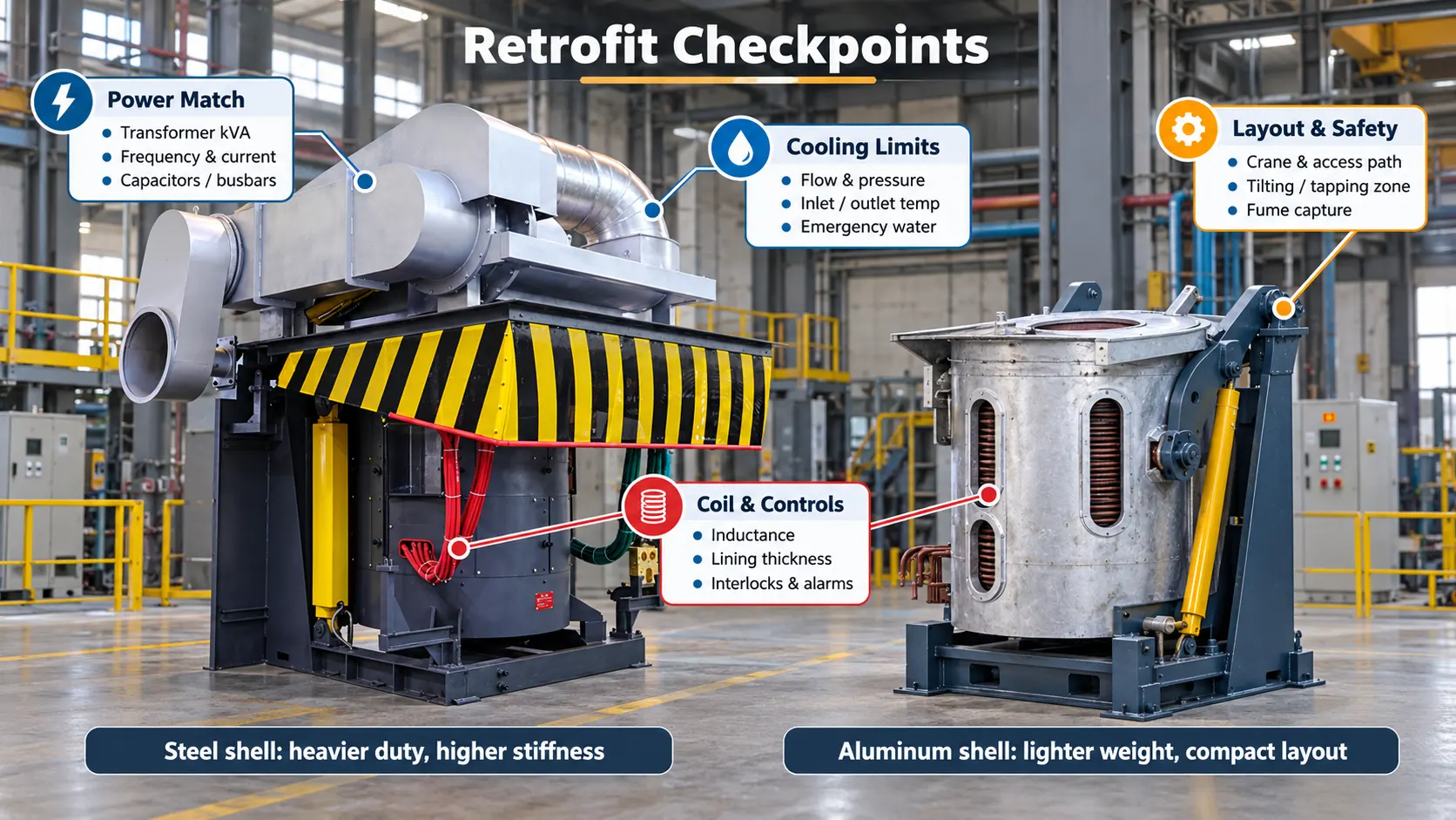
Before shipment, verify the foundation, lifting equipment, cable trenches, water lines, transformer space, and ventilation. Commissioning should include alignment, electrical checks, water-pressure testing, coil insulation, refractory installation, and controlled lining sintering.
Use an acceptance test that reflects production. Record melt and holding time, input power, power factor, cooling temperatures, water pressure, trips, leakage alarms, tilt behavior, restart time, and kWh per net tapped ton. Test both minimum holding and maximum permitted melt loads.
For a technical review, prepare furnace drawings, transformer nameplate, supply model, coil and capacitor data, cooling schematic, floor plan, production schedule, and installation photos. [Installation guidance] can frame the discussion, but the selected model specification controls.
The right induction furnace shell for a retrofit is the one that fits the complete system boundary. Choose steel when the verified duty requires greater structural support and repeated heavy operation; consider aluminum when compact layout, moderate duty, and lower structural weight are more important. In both cases, transformer margin, resonant compatibility, cooling, safety, and access must be checked before the shell is approved.
A project team can request a retrofit application review with furnace capacity, metal, production schedule, transformer data, coil dimensions, cooling conditions, layout drawings, and reuse scope.
Possibly, but only after checking coil inductance, operating frequency, current, capacitor values, transformer loading, cables, protection, cooling, and tilt controls. A shell change is not automatically a cabinet-only replacement.
No. It may suit heavier duty and repeated tilting, but the final result depends on the complete furnace, power, refractory, cooling, layout, and production configuration.
Provide flow, pressure, inlet temperature, water quality, heat-rejection capacity, pipe arrangement, emergency-water provision, and alarm or interlock requirements. Exact limits should be confirmed against the selected model.
Provide the floor plan, foundation and platform details, transformer and power-supply single-line diagram, coil and capacitor data, cooling schematic, cable routes, crane path, and tapping or ladle-access zones.
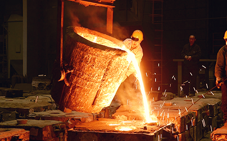
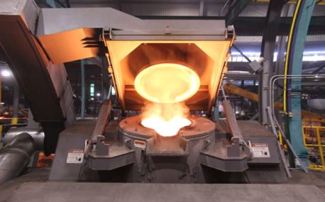
In the forging workshop, industrial furnaces smelt metals, including cupola, induction furnace, resistance furnace, electric arc furnace, vacuum furnace, open hearth furnace, crucible furnace, etc; There are sand mold drying furnace for baking sand mold, ferroalloy drying furnace and casting annealing furnace, etc; In the forging workshop, there are various heating furnaces for heating ingots or billets before forging and heat treatment furnaces for relieving stress after forging;
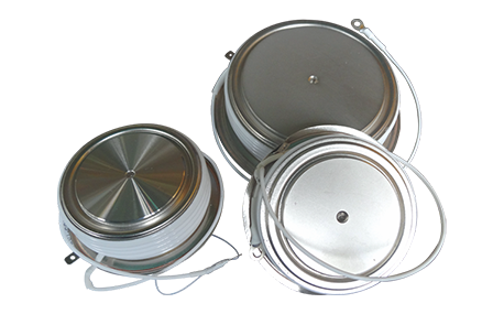
The most effective way for the failure of the medium frequency furnace is to use the low current experiment to judge whether it is the fault of the rectifier circuit or the fault of the inverter part. In the low current experiment, when the DC voltage is less than 513v, it indicates that there is a phase loss fault in the DC rectifier part. Check the specific thyristor fault, and the pulse breaking method should be used to judge whether it is the thyristor fault or there is no trigger pulse.
The most effective method for the failure of the intermediate frequency furnace is to use a small current experiment to judge whether the rectifier circuit is faulty or part of the inverter fault. When the DC current is less than 513 volts

Please send us your request and we will reply to you within 24 hours.
We will get in touch with you as soon as possible
