- Tel:+8616638907067
- Email:[email protected]
Induction furnace transformer capacity should be estimated from molten-metal output, specific energy demand, system losses, power factor, and simultaneous loads. Furnace tonnage alone is insufficient. Convert the production target to kilograms per hour, estimate useful process power, correct for losses, convert real input kW to kVA, and verify the electrical design with the equipment supplier excerpt …
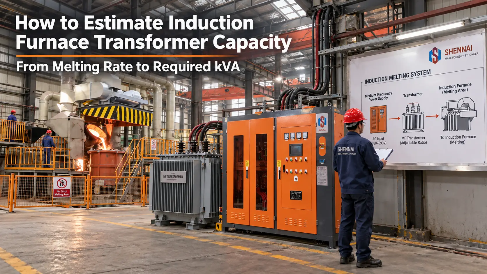
Induction furnace transformer capacity should be estimated from molten-metal output, specific energy demand, system losses, power factor, and simultaneous loads. Furnace tonnage alone is insufficient. Convert the production target to kilograms per hour, estimate useful process power, correct for losses, convert real input kW to kVA, and verify the electrical design with the equipment supplier and transformer engineer.
This approach creates a defensible starting point for specifying a medium-frequency power supply, its rectifier transformer, and the supporting electrical system. It is a budgetary method, not a final transformer design.
A 1-ton furnace describes vessel capacity, not qualified output per shift. Production changes with the metal, charge condition, tap temperature, heel practice, turnaround time, lining condition, and available power. Equal-capacity furnaces can therefore require different power supplies and transformers.
Define the target as qualified molten metal at the required temperature, not charged scrap. Record the alloy, cold-start or hot-heel practice, batch weight, melt time, non-powered time, hours per shift, and heats per day. For one supply feeding several furnaces, state which vessels must melt, hold, or sinter simultaneously.
For a single furnace, the first calculation is straightforward:
Required melting rate (kg/h) = qualified batch mass (kg) / total cycle time (h)
Total cycle time includes charging, slag removal, temperature checks, chemistry correction, tapping, and turnaround. For a daily target, divide qualified daily output by scheduled production hours, then confirm that the proposed heat cycle can sustain that average.
A useful preliminary relationship is:
Useful process power (kW) = melting rate (kg/h) x specific useful energy (kWh/kg)
Specific energy is not universal. It depends on the metal, starting and tapping temperatures, superheat, charge density, slag practice, and heat loss. Confirm whether the value represents useful energy at the metal or electrical energy at the incoming supply. Use comparable plant records, a validated heat balance, or a supplier calculation; do not transfer a figure between unlike metals or processes.
If the energy figure represents useful energy delivered to the metal, divide by expected overall system efficiency to estimate real electrical input:
Required real input (kW) = useful process power (kW) / expected overall efficiency
Overall efficiency includes power conversion, transmission, circuit tuning, coil-to-charge coupling, and thermal losses. Evaluate induction furnace electricity use per ton with the same operating boundary used in this calculation.
Transformers are rated in apparent power, while the process calculation produces real power. The preliminary conversion is:
Transformer load (kVA) = required real input (kW) / expected power factor
Use the power factor for the selected converter and operating range, not a generic value. It can change with loading, compensation, rectifier arrangement, control method, and grid conditions. SHENNAI lists high power factor for applicable series-inverter and IGBT configurations, but the project value must be confirmed for the proposed model and duty.
Calculated kVA is the furnace converter's operating load, not automatically the transformer nameplate rating. Final selection must cover duty, temperature rise, harmonic loading, impedance, site conditions, and the reserve required by the owner or transformer designer.
Define the transformer boundary before adding loads. Pumps, cooling-tower fans, hydraulics, fume extraction, charging equipment, and controls may be supplied elsewhere. If they share this transformer, convert each real-power load to kVA using its expected power factor and operating state.
List every furnace that can draw power simultaneously, including melting and holding modes.
Separate continuous loads from intermittent motors and starting events.
Apply diversity only when the control logic or operating procedure prevents simultaneous demand.
Check whether a multi-output system shares a fixed power limit or permits concurrent full-power operation.
Document future expansion so spare capacity is intentional.
A multi-furnace system can improve transformer utilization, but only when its controls and production schedule manage power allocation. Equipment count alone does not reveal maximum demand.
Assume a hypothetical project requires 1,000 kg/h of molten metal. Its heat balance uses 0.50 kWh/kg of useful energy, overall efficiency of 0.80, and power factor of 0.95. These examples are not SHENNAI performance guarantees.
Useful process power: 1,000 kg/h x 0.50 kWh/kg = 500 kW.
Required real input: 500 kW / 0.80 = 625 kW.
Converter-related transformer load: 625 kW / 0.95 = approximately 658 kVA.
If 50 kW of concurrent auxiliaries at 0.90 power factor share the transformer, add about 56 kVA, producing a preliminary connected load of about 714 kVA.
Do not simply round this result to a catalog rating. Give the assumptions to the power-supply and transformer suppliers so they can coordinate rating, secondary voltage, impedance, taps, harmonic duty, cooling, and protection.
Higher power increases current at a given voltage, affecting conductors, losses, switchgear, and cabinet design. Higher input voltage can reduce current, but insulation, rectifier design, plant standards, and maintainability also matter. SHENNAI product families cover multiple input voltages and 6- to 24-pulse arrangements, depending on configuration. These ranges are not automatic recommendations.
Pulse count and transformer winding arrangement affect rectification and harmonics. Larger projects may require a phase-shifting transformer and 12-pulse or higher-pulse solution, subject to utility limits and supplier design. For topology context, review SCR and IGBT selection factors. For IGBT-specific furnace ranges and production inputs, use the separate IGBT power-supply sizing checklist.
A transformer can have adequate kVA and still be mismatched. Secondary voltage must suit the converter; impedance affects voltage drop and fault current; and windings must match the pulse system. Harmonic heating, ambient temperature, altitude, enclosure, cooling, taps, short-circuit capacity, cable length, protection, and utility requirements can change the design.
Cooling is part of capacity planning. The cabinet, semiconductors, capacitors, reactor, busbars, and coil require specified water conditions. Low flow, high inlet temperature, scaling, or a poor circuit can limit output even when transformer kVA is sufficient.
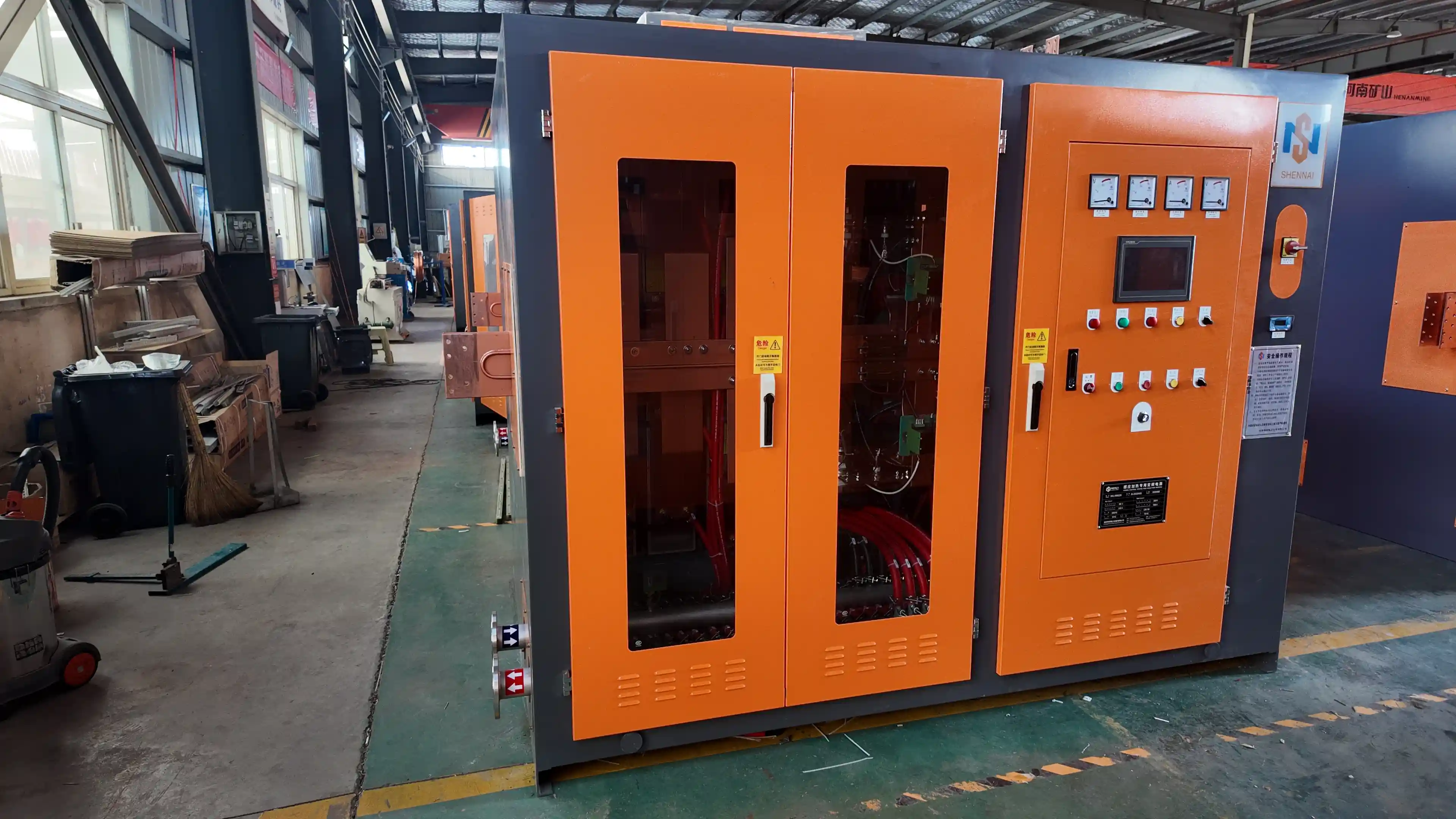
A useful RFQ connects production, process, electrical, and site data. Coordinate incoming voltage and current, rated power, medium-frequency voltage and current, operating frequency, and phase arrangement. Provide these inputs for final selection:
Metal, charge form, batch weight, starting and tap temperatures, and hot-heel practice.
Required qualified output per hour and per shift, expected melt time, and full cycle time.
Furnace quantity and capacity, simultaneous operating modes, and future expansion plan.
Primary voltage and frequency, harmonic limits, short-circuit level, and upstream transformer details.
Converter family, power factor, pulse arrangement, secondary voltage, impedance, and tap requirements.
Ambient temperature, altitude, indoor or outdoor installation, cooling-water temperature, pressure, flow, and water quality.
Auxiliary loads, motor starting, cable distances, protection, and local electrical requirements.
Induction furnace transformer sizing begins with qualified melting rate and ends with coordinated electrical design. Convert production into kg/h, apply process-specific energy and efficiency assumptions, translate input kW into kVA with the correct power factor, and include concurrent loads. Then validate voltage, pulse count, impedance, harmonics, cooling, duty, and site derating.
No. Tonnage describes vessel capacity, while transformer load depends on melting rate, metal, cycle time, energy demand, efficiency, power factor, simultaneous loads, and site conditions.
kW is real power used by the process and equipment. kVA is apparent power carried by the transformer. Dividing expected real input kW by the applicable power factor gives a preliminary kVA load.
Include auxiliaries only if they are supplied by the transformer being sized. Evaluate their actual simultaneous demand, power factor, motor starting, and diversity rather than adding every nameplate value blindly.
Not necessarily. Pulse count changes the rectifier and transformer winding arrangement and can improve harmonic performance. Final kVA depends on load and design conditions, while size and cost also depend on winding complexity, impedance, cooling, and standards.
For a project-specific fit check, request an application-specific electrical review and include the RFQ data above. SHENNAI can then evaluate the power-supply configuration against the required production duty and available plant power.
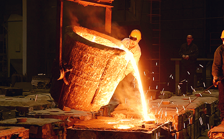
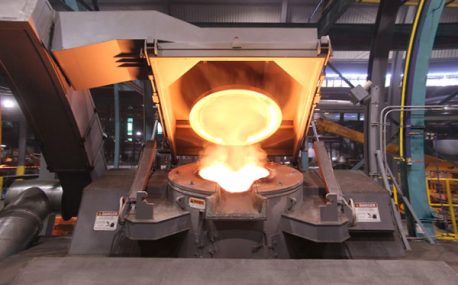
In the forging workshop, industrial furnaces smelt metals, including cupola, induction furnace, resistance furnace, electric arc furnace, vacuum furnace, open hearth furnace, crucible furnace, etc; There are sand mold drying furnace for baking sand mold, ferroalloy drying furnace and casting annealing furnace, etc; In the forging workshop, there are various heating furnaces for heating ingots or billets before forging and heat treatment furnaces for relieving stress after forging;
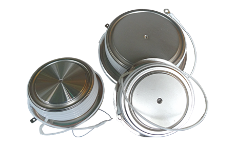
The most effective way for the failure of the medium frequency furnace is to use the low current experiment to judge whether it is the fault of the rectifier circuit or the fault of the inverter part. In the low current experiment, when the DC voltage is less than 513v, it indicates that there is a phase loss fault in the DC rectifier part. Check the specific thyristor fault, and the pulse breaking method should be used to judge whether it is the thyristor fault or there is no trigger pulse.
The most effective method for the failure of the intermediate frequency furnace is to use a small current experiment to judge whether the rectifier circuit is faulty or part of the inverter fault. When the DC current is less than 513 volts

Please send us your request and we will reply to you within 24 hours.
We will get in touch with you as soon as possible
