- Tel:+8616638907067
- Email:[email protected]
Before a medium-frequency power supply cabinet ships, its factory acceptance test should verify four things: the cabinet was built to the approved drawings, its electrical and cooling circuits are safe and traceable, its controls and protections respond correctly, and its configured power stage operates under an agreed test condition. A useful FAT is not a generic excerpt …
Before a medium-frequency power supply cabinet ships, its factory acceptance test should verify four things: the cabinet was built to the approved drawings, its electrical and cooling circuits are safe and traceable, its controls and protections respond correctly, and its configured power stage operates under an agreed test condition. A useful FAT is not a generic inspection form. It states the test setup, acceptance criteria, measured results, deviations, and items that must wait for site acceptance testing.
For foundries, this distinction matters because the cabinet is only one part of an induction melting system. Transformer capacity, furnace coil parameters, capacitor matching, cooling-water conditions, cables, switchgear, and the production load affect final performance. The pre-shipment FAT should prove the cabinet within a defined boundary without claiming that factory testing alone proves melt rate, energy consumption, or site integration.
The purchaser and manufacturer should approve the FAT procedure before the test date. The document should identify the cabinet model, equipment number, input and output ratings, inverter arrangement, output count, drawings, software version, test instruments, and test-load configuration. It should also define who will witness the test and what evidence must be included in the final report.
Each test needs a condition and a pass criterion. For example, a cooling pressure test needs the approved pressure, hold period, permitted pressure loss, and inspection method. A thermal run needs the load level, duration, ambient and water temperatures, measurement points, and allowable temperature limits. These values vary by design and contract; they should not be copied from another cabinet or treated as universal settings.
Begin with the cabinet de-energized. Verify enclosure dimensions, door operation, access clearances, ventilation openings, lifting points, and protective-earth bonding against the approved drawings. Confirm that the nameplate matches the contract and that component, instrument, terminal, button, water-inlet, and water-outlet labels are readable and consistent with the schematics.
Inside the cabinet, inspect busbar mating surfaces, supports, clearances, and phase identification. Rectifier and inverter modules, reactors, current transformers or Hall sensors, snubbers, capacitors, fiber-trigger modules, control boards, and terminals should be secure. Fiber-optic cables should be protected from heat, abrasion, sharp bends, and tension. Control wires should be numbered, routed, and separated from power conductors as required by the design.
Before auxiliary or main power is applied, confirm protective-earth continuity, point-to-point wiring, phase sequence, terminal tightness, fuse and breaker ratings, transformer taps, and control-voltage polarity. Compare installed parts with the bill of materials and drawings rather than relying only on panel labels.
Insulation resistance or dielectric tests should follow the approved design procedure and the applicable component instructions. Sensitive electronic boards, surge devices, measuring circuits, capacitors, and other parts may need isolation before a high-voltage test. The test voltage, duration, discharge method, and acceptable result must be specified for the actual cabinet. A generic hipot value can damage electronics or produce a misleading pass result.
Water-cooled copper pipes, flexible hoses, manifolds, reactors, semiconductor assemblies, and other cooled components should be inspected as a complete circuit. Fill and purge the system, apply the approved test pressure, hold it for the specified period, and inspect welds, joints, valves, and connections. Where the design uses separate cooling branches, test and identify them separately so a leak or blockage can be traced.
A pressure test checks leakage and pressure retention; it does not prove adequate operating flow. If the factory setup permits, also verify flow direction, pressure or flow switches, inlet and outlet temperature sensors, alarm thresholds, and trip logic under a controlled water supply. The selected pump, water quality, temperature, and heat-rejection capacity still need confirmation for the project. SHENNAI's industrial cooling tower range can be considered during system planning, but the final cooling specification must match the cabinet and furnace duty.
Apply auxiliary power first and check meters, indicators, HMI screens, fans, pumps or pump commands, contactors, communication links, and emergency stops. Verify that displayed signals correspond to the correct sensors and that command feedback matches the actual device state.
Protection testing should use safe signal injection or approved simulations wherever possible. Typical cabinet-level checks may include loss of cooling pressure or flow, high water temperature, overcurrent, short-circuit response, overvoltage, undervoltage, phase loss, door or access interlocks, and emergency shutdown. The exact list depends on the supplied configuration and should not be confused with transformer, furnace-leakage, or plant-level protections outside the cabinet boundary.
A powered FAT should begin only after mechanical, electrical, and cooling checks pass. Start with the approved auxiliary and low-power sequence, then increase power in controlled steps using a suitable resonant load or agreed test arrangement. A medium-frequency inverter should not be started into an unspecified open circuit merely to show that the cabinet turns on.
Record the test configuration and operating data at each step. Useful measurements include input voltage and current, DC-link values where applicable, output voltage and current, operating frequency, real power, cooling pressure or flow, inlet and outlet water temperature, and temperatures at defined electrical or cooling points. Instrument identification and calibration status should be included in the report.
For dual-output or multi-output cabinets, the FAT should verify every configured output path, selection command, electrical interlock, indication, and fault boundary. Confirm whether outputs may operate simultaneously, alternately, or only after isolation. Test prohibited switching states and verify that the control logic prevents an unsafe transition.
Power allocation should be checked against the approved total-power limit and transformer loading assumptions. A four-output system does not mean that four furnaces can each receive full cabinet power at the same time. Projects using 1-to-4 power-sharing systems should document the permitted operating combinations, holding priorities, transfer sequence, and behavior when one branch faults.
The FAT report should contain the approved procedure, signed results, instrument list, photographs where useful, protection settings, software or parameter backup, serial numbers, cooling-test record, torque or connection-inspection record, and a list of deviations. Failed items should remain open until corrected and retested. Any accepted deviation needs written disposition, not a verbal note.
Keep a separate SAT list for incoming power, transformer interfaces, site grounding, external cables, cooling-water quality and capacity, furnace matching, remote I/O, emergency systems, and loaded melting performance. This creates a clear handover instead of using FAT as a substitute for commissioning.
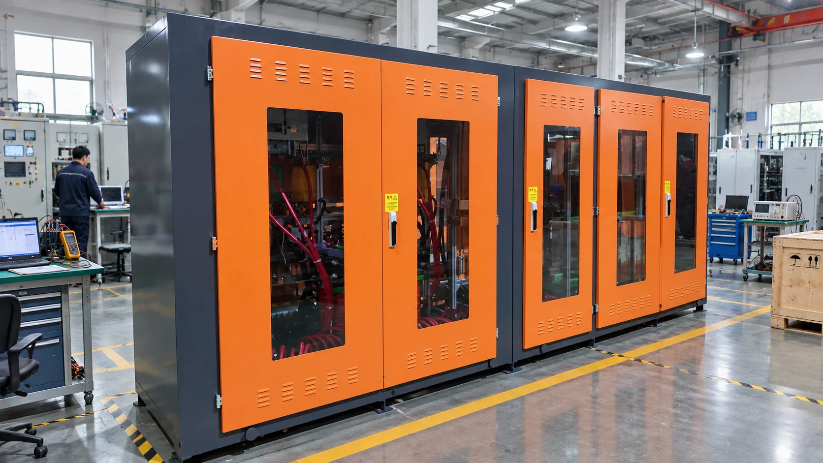
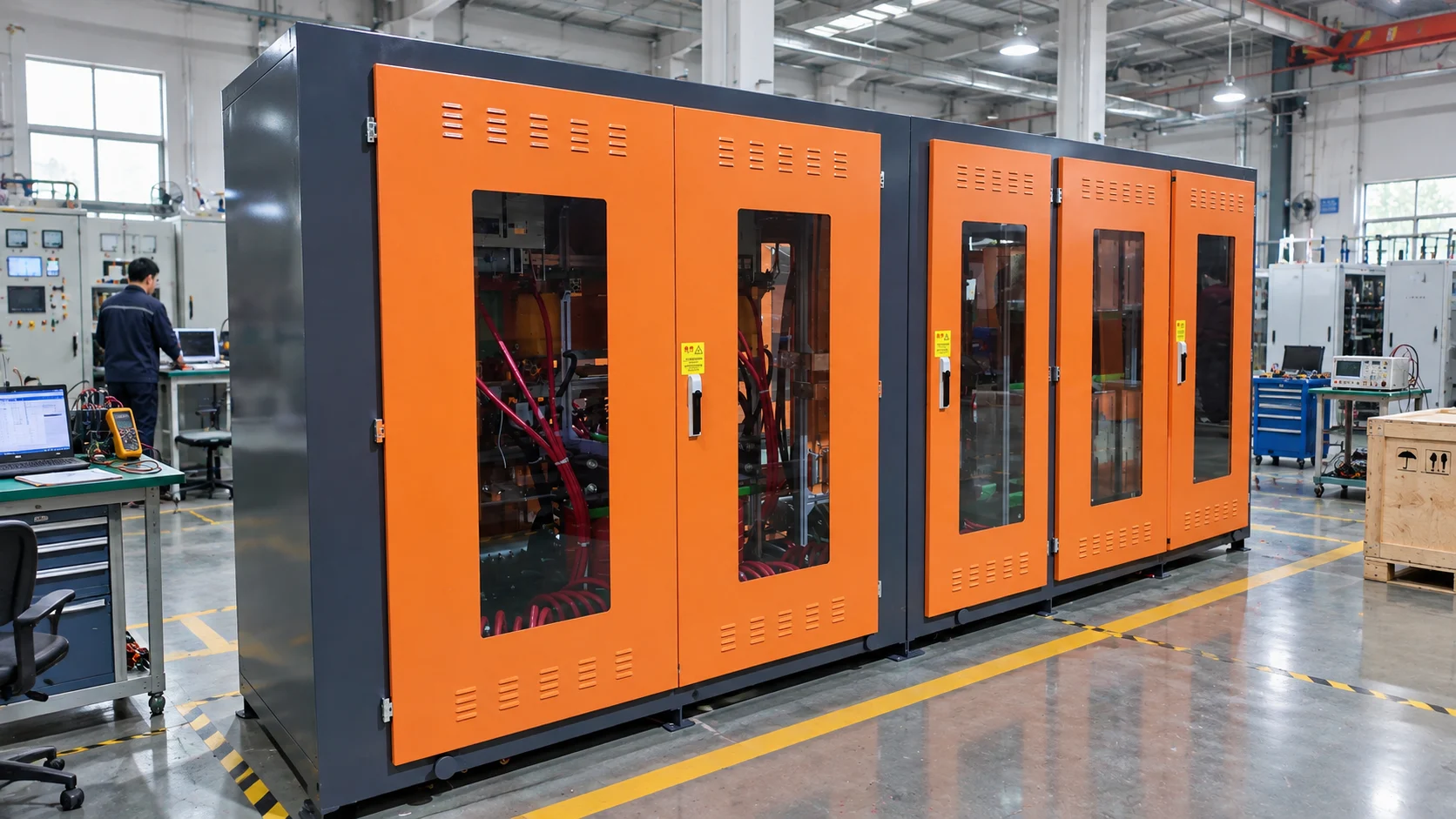
A real cabinet photograph can help a purchaser review visible features such as enclosure arrangement, access doors, inspection windows, meters, HMI, pushbuttons, labels, and internal conductor routing. It is supporting context, not proof that the cabinet passed FAT; the signed results and measured data provide that evidence. SHENNAI's medium-frequency power supply range includes configurations for induction melting applications, with final ratings and functions confirmed for each project.
A pre-shipment FAT for a medium-frequency power supply cabinet should answer a simple question: is this specific cabinet complete, safe, correctly configured, functionally verified, and documented for shipment under the agreed test conditions? The strongest FAT packages combine de-energized inspection, cooling verification, protection simulation, controlled powered testing, and traceable release records.
They also state their limits. Site transformer conditions, furnace matching, cooling capacity, production duty, and melt performance remain part of installation, commissioning, and SAT. Keeping those boundaries clear reduces disputes and makes the final start-up more efficient.
No. FAT verifies the cabinet at the manufacturer's facility within an agreed test boundary. SAT verifies installation, site utilities, external interfaces, furnace matching, and operation after delivery.
No. Test voltage, duration, isolated components, and pass criteria depend on the cabinet design, equipment rating, electronic devices, and approved procedure.
No. It primarily verifies leakage and pressure retention. Operating flow, water temperature, water quality, pump head, and heat rejection must also be checked for the actual system.
Usually not by itself. Melt rate depends on transformer capacity, furnace and coil matching, charge material, operating practice, cooling conditions, and the complete site system. It should be verified under an agreed production acceptance test when required.
To prepare a cabinet-specific inspection and acceptance boundary, provide the required power, input voltage, transformer data, inverter type, output count, furnace and coil information, cooling conditions, protection philosophy, communication requirements, and witness-test expectations, then request a project-specific FAT review.
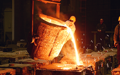
In the forging workshop, industrial furnaces smelt metals, including cupola, induction furnace, resistance furnace, electric arc furnace, vacuum furnace, open hearth furnace, crucible furnace, etc; There are sand mold drying furnace for baking sand mold, ferroalloy drying furnace and casting annealing furnace, etc; In the forging workshop, there are various heating furnaces for heating ingots or billets before forging and heat treatment furnaces for relieving stress after forging;
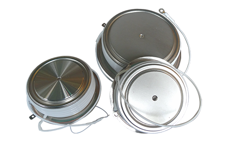
The most effective way for the failure of the medium frequency furnace is to use the low current experiment to judge whether it is the fault of the rectifier circuit or the fault of the inverter part. In the low current experiment, when the DC voltage is less than 513v, it indicates that there is a phase loss fault in the DC rectifier part. Check the specific thyristor fault, and the pulse breaking method should be used to judge whether it is the thyristor fault or there is no trigger pulse.
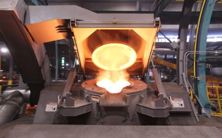
The most effective method for the failure of the intermediate frequency furnace is to use a small current experiment to judge whether the rectifier circuit is faulty or part of the inverter fault. When the DC current is less than 513 volts

Please send us your request and we will reply to you within 24 hours.
We will get in touch with you as soon as possible
