- Tel:+8613007564317
- Email:[email protected]
First, check the power switch and control switch to see if they are closed; If the control switch is turned on and gives an alarm, the following processing shall be carried out according to the alarm information.
(1) The phase loss alarm (OP) light is on. Check whether the fuse melt of the main circuit is blown; If it is normal, check the three-phase incoming line and use the AC voltage -oov gear of the multimeter to check whether it is lack of phase. If it is normal, check whether the cathode (k) wiring of rectifier thyristor is open circuit.
(2) The water shortage alarm (V (RPL) light is on. Check whether the water pump, water pipeline and electric contact pressure gauge are normal.
(3) The undervoltage alarm (LV) light on the main control board is on. Check whether the control power transformer is normal. If it is normal, check whether the filter capacitor on the main control board has leakage or failure. If it is normal, use the AC voltage 50V gear of the multimeter to check whether the secondary voltage (17V) of the control power transformer is normal.
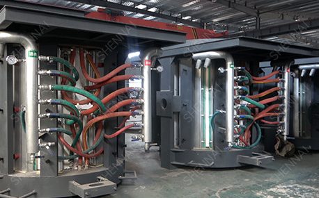
(4) The over voltage (OV) lamp is on. Observe whether there is ignition between the smelting workpiece and the induction coil. If there is ignition, adjust the gap between the induction coil and the smelting workpiece. Observe whether the induction coil ignites with the oxide skin. If so, clean the oxide skin. Check whether the connecting copper bar screws of induction coil, compensation capacitor and main circuit are loose and ignited. If the screws are loose and ignited, tighten the screws.
If all the above checks are normal, check whether the inverter thyristor (KK) is damaged. Using a multimeter R × 1 gear detection: if the resistance between the cathode and anode of the thyristor is zero, the thyristor is damaged and replaced. If one (two) inverter thyristors of intermediate frequency power supply are damaged, the front angle of inverter is greater than or equal to 2, and the ratio of DC current to DC voltage is much larger than normal, the front angle of inverter should be readjusted to 1.5.
(5) OC (overflow) light is on. The fault causes of OC (overcurrent) light on are: there are short circuit points in the induction coil, compensation capacitor and its connecting copper bar; Two (four) inverter thyristors are damaged; The inverter thyristor has poor characteristics. If the OV / OC light is on at the same time, it is mainly overvoltage during maintenance. Use the rxlk gear of the multimeter to detect whether the compensation capacitor has breakdown. If the capacitor cannot be charged and discharged normally or the resistance value is zero, it is the fault of the compensation capacitor. If the above inspection is normal, it is preliminarily judged that the water-cooling cable is faulty. Use the multimeter RXL gear to detect the resistance of the water-cooling cable. If there is a resistance value, the water-cooling cable is faulty. It is difficult to detect water-cooled cables. The most direct and effective method is to use the replacement method, that is, to temporarily replace water-cooled cables with power cables. If the water-cooled cable is normal, check whether there is any metal object between the turns of the induction coil that causes the turn to turn short circuit; If it is normal, check if the intermediate frequency transformer is faulty. If it is faulty, replace it with a new intermediate frequency transformer.
Previous: Why is the discharge inductance hot

The total efficiency of the induction heating system, that is the ratio of the power obtained on the workpiece to the input power of the power supply, is related to the following four factors:
a 5T medium frequency furnace always burns KK thyristor (2500A / 3000V) and always burns the same thyristor. What’s the matter?
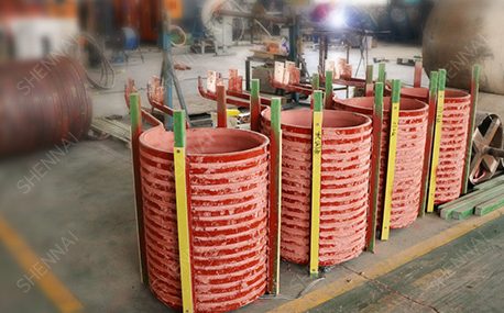
Induction heating equipment with high relative power and low frequency shall be selected for large workpieces, bars and solid materials; For small workpieces, pipes, plates, gears, etc., induction heating equipment with low relative power and high frequency shall be selected.
Please send us your request and we will reply to you within 24 hours.
We will get in touch with you as soon as possible